Infiniti F50. Manual - part 791
HEATED SEAT
SE-155
C
D
E
F
G
H
J
K
L
M
A
B
SE
Rear Heated Seat Switch Low Circuit Inspection
EIS003W3
1.
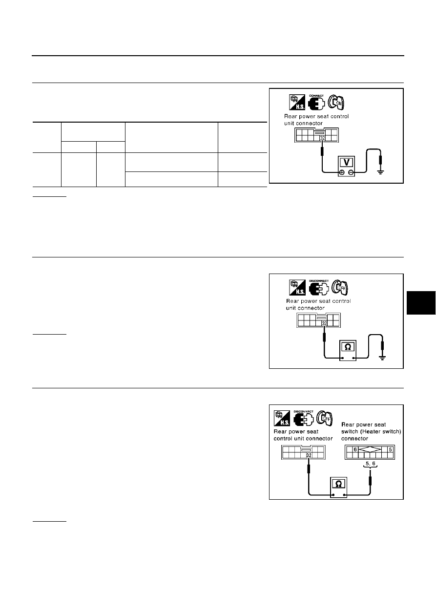
CHECK REAR HEATER SWITCH POWER SUPPLY
1.
Turn ignition switch ON.
2.
Check voltage between rear power seat control unit connector
and ground.
OK or NG
OK
>> Replace rear power seat control unit.
NG
>> When turn ignition switch ON and heater switch LOW, check the following.
●
When voltage is approx. 0V, GO TO 2.
●
When voltage is approx. 5V, GO TO 3.
2.
CHECK REAR POWER SEAT SWITCH (HEATER SWITCH) HEATER HARNESS
1.
Turn ignition switch OFF.
2.
Disconnect rear seat control unit connector and rear power seat
switch (heater switch) connector.
3.
Check continuity between rear seat control unit connector B163
(LH), B363 (RH) terminal 32 (LG/W) and ground.
OK or NG
OK
>> Replace rear power seat control unit.
NG
>> Repair or replace harness between rear power seat con-
trol unit and rear power seat switch (heater switch).
3.
CHECK REAR POWER SEAT SWITCH (HEATER SWITCH) HEATER HARNESS
1.
Turn ignition switch OFF.
2.
Disconnect rear power seat control unit connector and rear
power seat switch (heater switch) connector.
3.
Check continuity between rear power seat control unit connector
B163 (LH), B363 (RH) terminal 32 (LG/W) and rear power seat
switch (heater switch) connector D55 (LH), D75 (RH) terminal 5
(L/W) (LH), 6 (Y/R) (RH).
OK or NG
OK
>> GO TO 4.
NG
>> Repair or replace harness between rear power seat control unit and rear power seat switch
(heater switch).
Con-
nector
Terminal
(Wire color)
Condition
Voltage (V)
(Approx.)
(+)
(–)
B163
(LH),
B363
(RH)
32 (LG/W)
Ground
Turn ignition switch ON.
Heater switch LOW.
0
Heater switch OFF.
5
PIIA4043E
32 (LG/W)
−
Ground
:Continuity should not exist
PIIA4044E
Rear seat LH
32 (LG/W)
−
5 (L/W)
:Continuity should exist
Rear seat RH
32 (LG/W)
−
6 (Y/R)
:Continuity should exist
PIIA4045E