Infiniti F50. Manual - part 610


  Index      Infiniti     Infiniti F50 - service repair manual 2006 year


Search            


Content   ..  608  609  610  611   ..


Infiniti F50. Manual - part 610


REVERSE INTERLOCK DOOR MIRROR SYSTEM

GW-111

C

D

E

F

G

H

J

K

L

M

A

B

GW

Mirror Sensors Circuit Inspection 

EIS0011N

1. 

DOOR MIRROR FUNCTION INSPECTION

Check the following items.

Operation malfunction caused by a foreign object caught in door mirror face edge.

Operation malfunction in memory control

NOTE:
If a door mirror face position is set to an implausible angle, the set position may not be reproduced.

OK or NG?

OK

>> GO TO 2.

NG

>> Repair the malfunctioning parts, and check the symptom again.

2. 

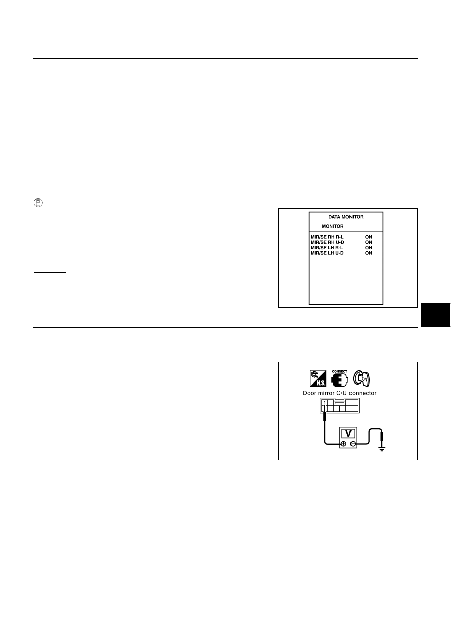
MIRROR SENSOR INSPECTION

With CONSULT–II

Check that "ON" is displayed on “MIR/SE RH R-L ”, “MIR/
SE RH U-D
 ” or “MIR/SE LH R-L ”, “MIR/SE LH U-D ” in the
DATA MONITOR. Refer to 

GW-95, "DATA MONITOR"

 .

NOTE:
It CONSULT-II is not available, skip this procedure and go to the next
step.

Question

OK

>> System is OK.

NG

>> GO TO 3.

3. 

MIRROR SENSOR POWER SUPPLY INSPECTION

1.

Turn ignition switch ON.

2.

Check voltage between door mirror control unit connector D5 (deiver side), D35 (passenger side) terminal
1 and ground.

OK or NG

OK

>> GO TO 4

NG

>> Replace door mirror control unit.

PIIB0342E

1 (W/L) – Ground

:Approx. 5V

PIIA4604E

GW-112

REVERSE INTERLOCK DOOR MIRROR SYSTEM

4. 

MIRROR SENSOR GROUND CIRCUIT INSPECTION

1.

Turn ignition switch OFF.

2.

Check continuity between door mirror control unit connector D5 (deiver side), D35 (passenger side) termi-
nal 2 and ground.

OK or NG

OK

>> GO TO 5

NG

>> Replace door mirror control unit.

5. 

HARNESS CONTINUITY INSPECTION 1

1.

Disconnect door mirror control unit connector D5 (driver side), D35 (passenger side) and door mirror con-
nector D2 (driver side), D32 (passenger side).

2.

Check continuity between door mirror control unit connector D5
(driver side), D35 (passenger side) terminal 1, 2 and door mirror
connector D2 (driver side), D32 (passenger side) terminal 10,
16.

OK or NG

OK

>> GO TO 6

NG

>> Repair or replace harness.

6. 

HARNESS CONTINUITY INSPECTION 2

1.

Disconnect door mirror control unit connector D5 (driver side), D35 (passenger side) and door mirror con-
nector D2 (driver side), D32 (passenger side).

2.

Check continuity between door mirror control unit connector D5 (driver side), D35 (passenger side) termi-
nals 5, 6 and door mirror connector D2 (driver side), D32 (passenger side) terminals 12, 14.

3.

Check continuity between door mirror control unit connector D5
(driver side), D35 (passenger side) terminals 5, 6 and ground.

OK or NG?

OK

>> GO TO 7.

NG

>> Repair or replace harness.

2 (Y) – Ground 

:Continuity should exist.

PIIA4605E

1 (W/L) – 16 (W/L)

:Continuity should exist.

2 (Y) – 10 (Y)

:Continuity should exist.

PIIA4606E

5 (L/Y) – 14 (L/Y)

:Continuity should exist.

6 (G) – 12 (G)

:Continuity should exist.

5 (L/Y) – Ground

:Continuity should not exist.

6 (G) – Ground

:Continuity should not exist.

PIIA3540E

REVERSE INTERLOCK DOOR MIRROR SYSTEM

GW-113

C

D

E

F

G

H

J

K

L

M

A

B

GW

7. 

MIRROR SENSOR SIGNAL INSPECTION

1.

Connect  door mirror control unit D5 (driver side), D35 (passenger side) and door mirror D2 (driver side),
D32 (passenger side) connectors.

2.

Turn ignition switch ON.

3.

Check voltage between door mirror control unit connector D5 (driver side), D35 (passenger side) termi-
nals 5, 6and ground.

OK or NG?

OK

>> Replace the door mirror control unit.

NG

>> Replace the door  mirror.

Con-

nector

Terminals (Wire color)

Condition

Voltage [V]

(Approx.)

(+)

(–)

D5

D35

5(L/Y)

Ground

When motor is 
activated
(UP/ DOWN)

Changes between 

4 (close to peak) – and

 0.5 (close to valley)

6(G)

When motor is 
activated
(LEFT/ RIGHT)

Changes between 

4 (close to right edge) – and 

0.5 (close to left edge)

PIIA3541E

GW-114

DOOR MIRROR

DOOR MIRROR

PFP:96301

Removal and Installation

EIS000OE

NOTE:
Be careful not to damage the mirror bodies.

REMOVAL

1.

Remove the front door finisher and door sash cover. Refer to 

EI-30, "Removal and Installation"

 .

2.

Remove the door mirror harness connector.

3.

Loosen the door mirror mounting nuts, and remove the door mirror assembly.

INSTALLATION

Install in the reverse order of removal.

PIIA0046E


Content   ..  608  609  610  611   ..