Infiniti F50. Manual - part 531
ENGINE ROOM COVER
EM-11
C
D
E
F
G
H
I
J
K
L
M
A
EM
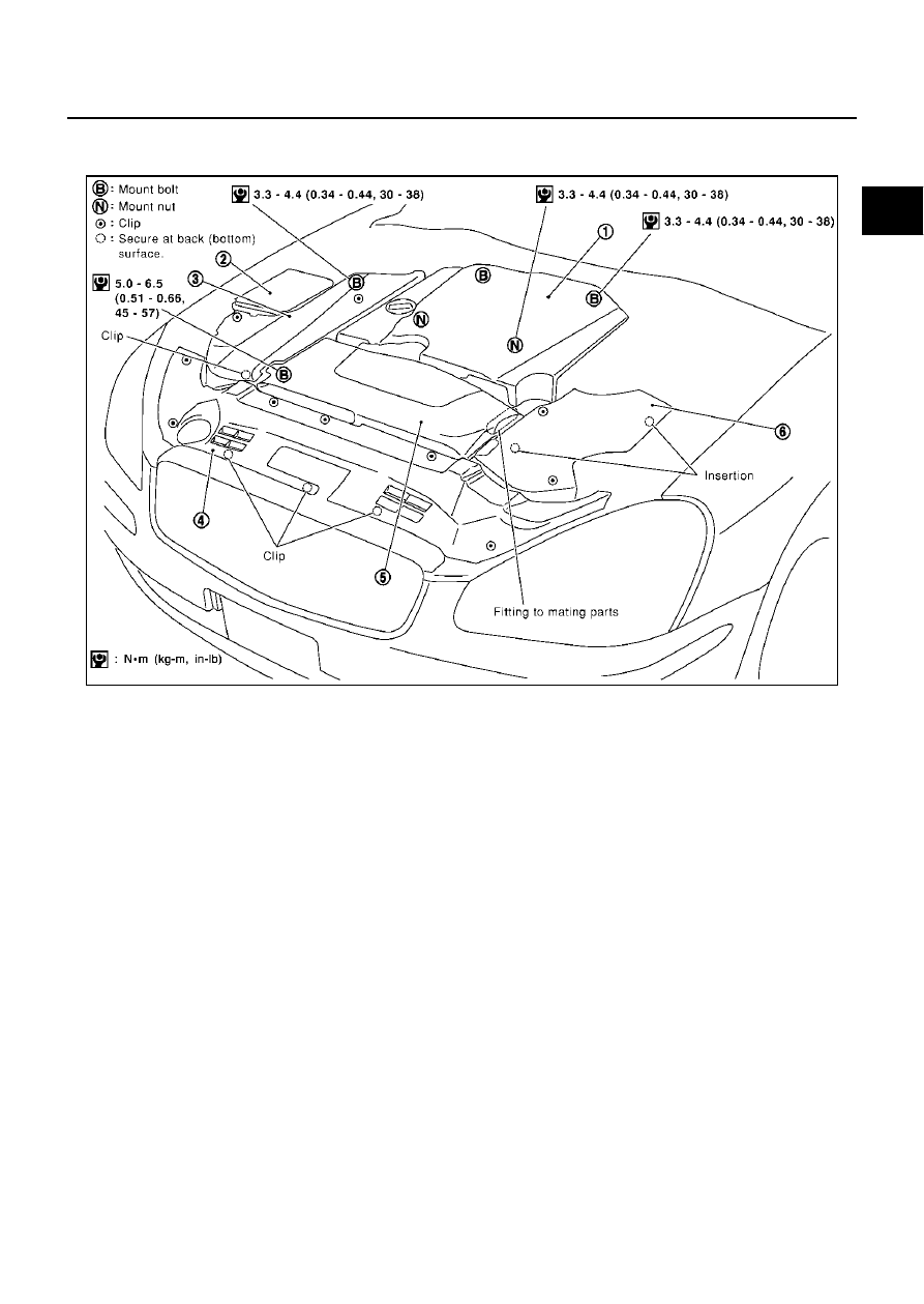
ENGINE ROOM COVER
PFP:14049
Removal and Installation
EBS001ZC
REMOVAL
●
Remove clips on back with clip driver.
CAUTION:
Do not damage or scratch cover when installing or removing.
●
Major parts and inspection points under each cover are as follows; (numbered as in illustration)
1.
Upper side of engine assembly, power steering reservoir tank, cooling fan reservoir tank
2.
Relay
3.
Battery, relay box
4.
Cooling fan fluid cooler, power steering fluid cooling tube
5.
Engine assembly front side, drive belts, cooling fan
6.
Mass air flow sensor, air cleaner case
INSTALLATION
Install in the reverse order of removal.
PBIC0196E
1.
Engine cover
2.
Relay box
3.
Battery cover
4.
Front air guide
5.
Air duct (inlet)
6.
Air cleaner cover