Infiniti F50. Manual - part 419
DTC P0340 CMP SENSOR (PHASE)
EC-317
C
D
E
F
G
H
I
J
K
L
M
A
EC
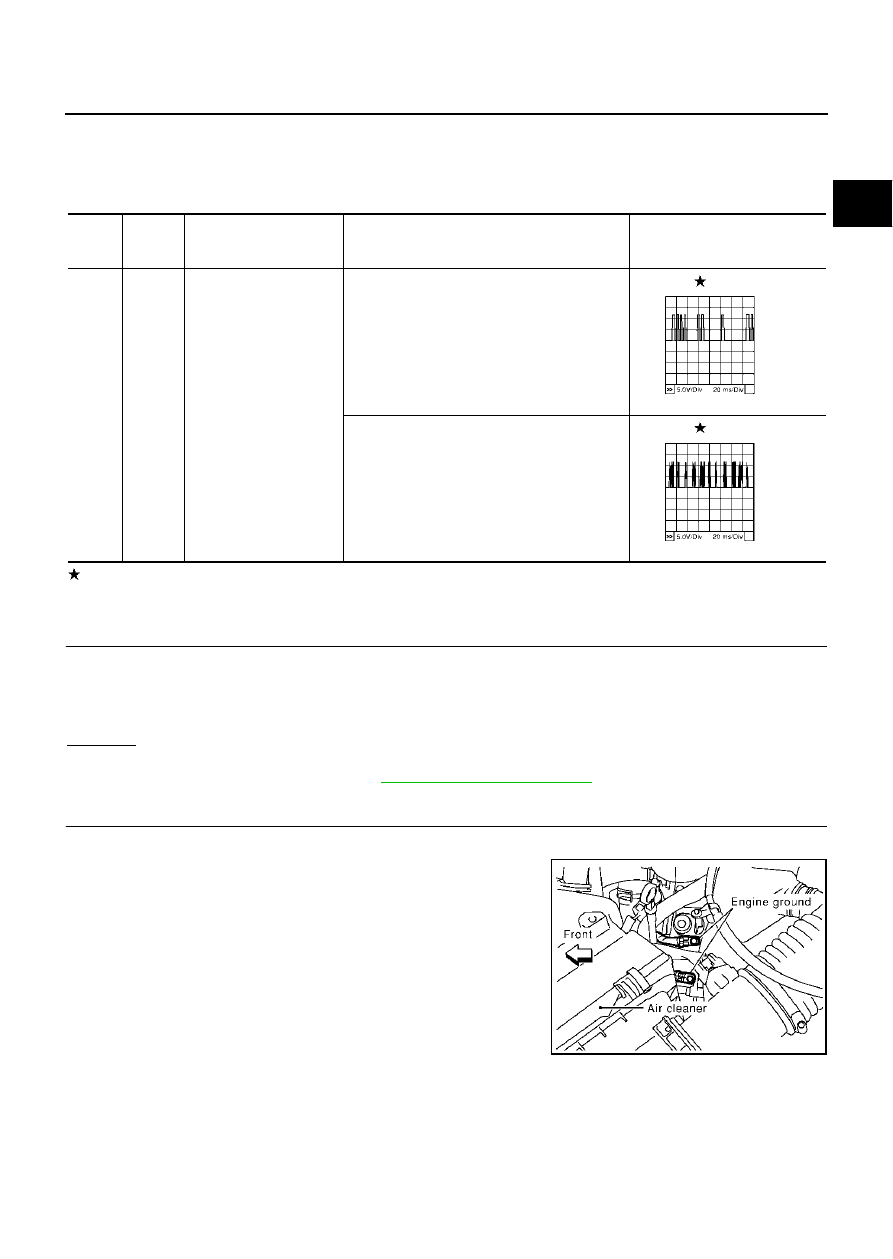
Specification data are reference values and are measured between each terminal and ground.
Pulse signal is measured by CONSULT-II.
CAUTION:
Do not use ECM ground terminals when measuring input/output voltage. Doing so may result in dam-
age to the ECM's transistor. Use a ground other than ECM terminals, such as the ground.
: Average voltage for pulse signal (Actual pulse signal can be confirmed by oscilloscope.)
Diagnostic Procedure
EBS00ME2
1.
CHECK STARTING SYSTEM
Turn ignition switch to “START” position.
Yes or No
Yes
>> GO TO 2.
No
>> Check starting system. (Refer to
2.
RETIGHTEN GROUND SCREWS
1.
Turn ignition switch “OFF”.
2.
Loosen and retighten engine ground screws.
>> GO TO 3.
TER-
MINAL
NO.
WIRE
COLOR
ITEM
CONDITION
DATA (DC Voltage)
84
L/W
Camshaft position sensor
(PHASE)
[Engine is running]
●
Warm-up condition
●
Idle speed
NOTE:
The pulse cycle changes depending on rpm at
idle.
1.0 - 4.0V
[Engine is running]
●
Engine speed is 2,000 rpm.
1.0 - 4.0V
PBIB0056E
PBIB0057E
Does the engine turn over?
Does the starter motor operate?
PBIB0011E