Infiniti F50. Manual - part 420


  Index      Infiniti     Infiniti F50 - service repair manual 2006 year


Search            


Content   ..  418  419  420  421   ..


Infiniti F50. Manual - part 420


DTC P0420, P0430 THREE WAY CATALYST FUNCTION

EC-321

C

D

E

F

G

H

I

J

K

L

M

A

EC

9.

Rev engine up to 2,000 to 3,000 rpm and maintain it until
“INCMP” of “CATALYST” changes to “CMPLT” (It will take
approximately 5 minutes).
If not “CMPLT”, perform the following.

a.

Turn ignition switch “OFF” and leave the vehicle in a cool place
(soak the vehicle).

b.

Turn ignition switch “ON” and select “COOLAN TEMP/S” in
“DATA MONITOR” mode with CONSULT-II.

c.

Start engine and warm it up while monitoring “COOLAN TEMP/
S” indication on CONSULT-II.

d.

When “COOLAN TEMP/S” indication reaches to 70 

°

C (158 

°

F),

go to step 3.

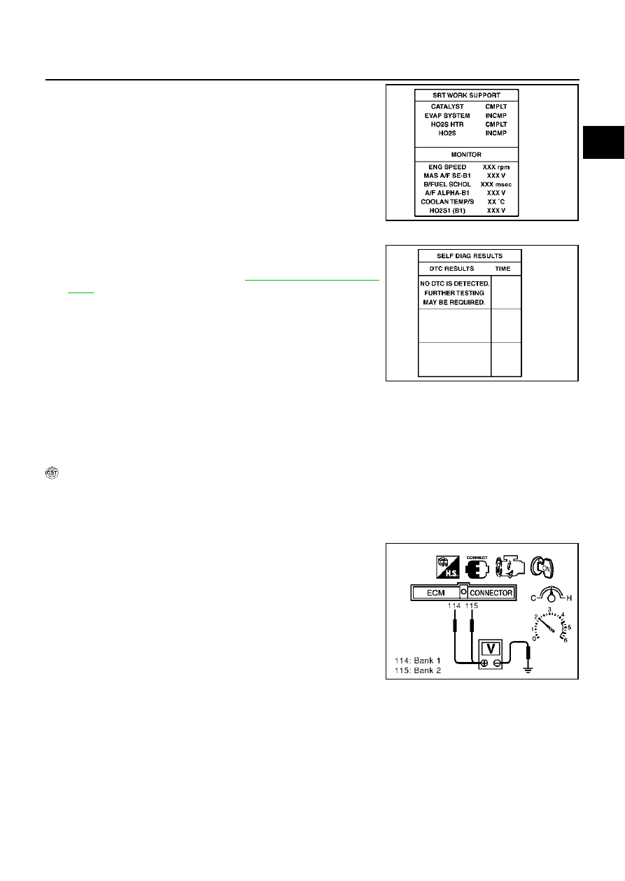
10. Select “SELF-DIAG RESULTS” mode with CONSULT-II.

11. Confirm that the 1st trip DTC is not detected.

If the 1st trip DTC is detected, go to 

EC-322, "Diagnostic Proce-

dure"

 .

Overall Function Check

EBS00ME7

Use this procedure to check the overall function of the three way catalyst 1. During this check, a DTC might
not be confirmed.

CAUTION:

Always drive vehicle at a safe speed.

 WITH GST

1.

Start engine and warm it up to the normal operating temperature.

2.

Turn ignition switch “OFF” and wait at least 10 seconds.

3.

Start engine and keep the engine speed between 3,500 and 4,000 rpm for one minute under no load.

4.

Let engine idle for one minute.

5.

Set voltmeters probes between ECM terminals 114 [HO2S1
(bank 1) signal], 115 [HO2S1 (bank 2) signal] and engine
ground, and ECM terminals 123 [HO2S2 (bank 1) signal], 124
[HO2S2 (bank 2) signal] and engine ground.

6.

Keep engine speed at 2,000 rpm constant under no load.

SEF941Z

SEF535Z

PBIB0063E

EC-322

DTC P0420, P0430 THREE WAY CATALYST FUNCTION

7.

Make sure that the voltage switching frequency (high & low)
between ECM terminals 123 and engine ground, or 124 and
engine ground is very less than that of ECM terminals 114 and
engine ground, or 115 and engine ground.
Switching frequency ratio = A/B
A: Heated oxygen sensor 2 voltage switching frequency
B: Heated oxygen sensor 1 voltage switching frequency
This ratio should be less than 0.75.
If the ratio is greater than above, it means three way catalyst
does not operate properly. Go to 

EC-322, "Diagnostic Proce-

dure"

 .

NOTE:
If the voltage at terminal 114 or 115 does not switch periodically more than 5 times within 10 seconds at step 5,
perform trouble diagnosis for “DTC P0133, P0153” first. (See 

EC-221

 .)

Diagnostic Procedure

EBS00ME8

1. 

CHECK EXHAUST SYSTEM

Visually check exhaust tubes and muffler for dent.

OK or NG

OK

>> GO TO 2.

NG

>> Repair or replace.

2. 

CHECK EXHAUST GAS LEAK

1.

Start engine and run it at idle.

2.

Listen for an exhaust gas leak before the three way catalyst (Manifold).

OK or NG

OK

>> GO TO 3.

NG

>> Repair or replace.

3. 

CHECK INTAKE AIR LEAK

Listen for an intake air leak after the mass air flow sensor.

OK or NG

OK

>> GO TO 4.

NG

>> Repair or replace.

PBIB0068E

SEC502D

DTC P0420, P0430 THREE WAY CATALYST FUNCTION

EC-323

C

D

E

F

G

H

I

J

K

L

M

A

EC

4. 

CHECK IGNITION TIMING

Check the following items. Refer to 

EC-82, "Basic Inspection"

 .

OK or NG

OK

>> GO TO 5.

NG

>> Follow th

EC-82, "Basic Inspection"

 .

5. 

CHECK INJECTORS

1.

Stop engine and then turn ignition switch “ON”.

2.

Check voltage between ECM terminals 5, 6, 7, 13, 14, 15, 16, 17
and ground with CONSULT-II or tester.

3.

Refer to Wiring Diagram for Injectors

EC-654

 .

OK or NG

OK

>> GO TO 6.

NG

>> Perform 

EC-657, "Diagnostic Procedure"

 .

6. 

CHECK IGNITION SPARK

1.

Turn ignition switch “OFF”.

2.

Disconnect ignition coil assembly from rocker cover.

3.

Connect a known-good spark plug to the ignition coil assembly.

4.

Disconnect all injector harness connectors.

5.

Place end of spark plug against a suitable ground and crank engine.

6.

Check for spark.

OK or NG

OK

>> GO TO 7.

NG

>> Check ignition coil with power transistor and their circuit.

Refer to 

EC-641, "IGNITION SIGNAL"

 .

Items

Specifications

Ignition timing

12

°


±

 5

°

 BTDC (in “P” or “N” position)

Target idle speed

650 

±

 50 rpm (in “P” or “N” position)

Voltage: Battery voltage

PBIB0069E

SEF575Q

EC-324

DTC P0420, P0430 THREE WAY CATALYST FUNCTION

7. 

CHECK INJECTOR

1.

Turn ignition switch “OFF”.

2.

Remove injector assembly.
Refer to 

EM-31, "FUEL INJECTOR AND FUEL TUBE"

 .

Keep fuel hose and all injectors connected to injector gallery.

3.

Reconnect all injector harness connectors disconnected.

4.

Disconnect all ignition coil harness connectors.

5.

Turn ignition switch “ON”.
Make sure fuel does not drip from injector.

OK or NG

OK (Does not drip.)>>GO TO 8.
NG (Drips.)>>Replace the injector(s) from which fuel is dripping.

8. 

CHECK INTERMITTENT INCIDENT

Refer to 

EC-132, "TROUBLE DIAGNOSIS FOR INTERMITTENT INCIDENT"

 .

Trouble is fixed.>>INSPECTION END
Trouble is not fixed.>>Replace three way catalyst assembly.


Content   ..  418  419  420  421   ..