Infiniti F50. Manual - part 319
VEHICLE INFORMATION AND INTEGRATED SWITCH SYSTEM /WITHOUT
NAVIGATION SYSTEM
DI-119
C
D
E
F
G
H
I
J
L
M
A
B
DI
Power Supply and Ground Circuit Inspection for AV Control Unit
EKS006E1
1.
CHECK FUSE
Check AV control unit fuses are not blown.
OK or NG
OK
>> GO TO 2.
NG
>> If fuse is blown, be sure to eliminate cause of malfunction before installing new fuse. Refer to
2.
CHECK POWER SUPPLY CIRCUIT
1.
Disconnect AV control unit connector.
2.
Check voltage between AV control unit and ground.
OK or NG
OK
>> GO TO 3.
NG
>> Check harness for open or short between AV control unit and fuse.
3.
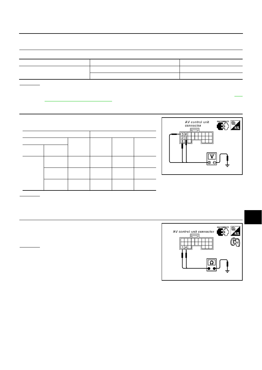
CHECK GROUND CIRCUIT
Check continuity between AV control unit harness connector M78
terminal 1 (B), 4 (B) and ground.
OK or NG
OK
>> Inspection end.
NG
>> Repair harness or connector.
Unit
Power source
Fuse No.
AV control unit
Battery power
47
Ignition switch ACC or ON
21
Terminals
Ignition switch position
(+)
(-)
OFF
ACC
ON
Connector
Terminal
(Wire color)
M78
2 (SB)
Ground
Battery
voltage
Battery
voltage
Battery
voltage
3 (SB)
Ground
Battery
voltage
Battery
voltage
Battery
voltage
6 (L/OR)
Ground
0V
Battery
voltage
Battery
voltage
SKIA3607E
Continuity should exist.
SKIA3608E