Infiniti F50. Manual - part 318
VEHICLE INFORMATION AND INTEGRATED SWITCH SYSTEM /WITHOUT
NAVIGATION SYSTEM
DI-115
C
D
E
F
G
H
I
J
L
M
A
B
DI
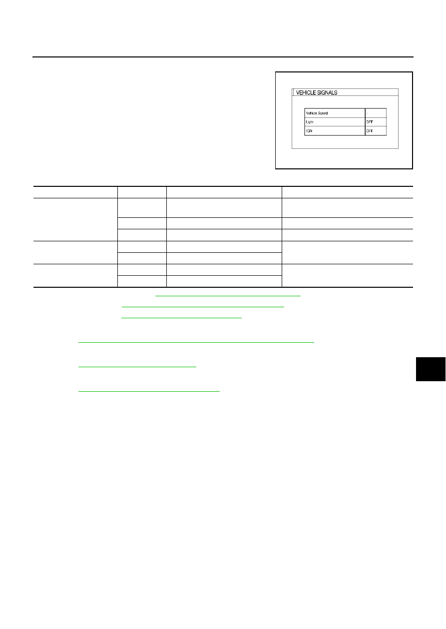
VEHICLE SIGNALS
●
A comparison check can be made of each actual vehicle signal
and the signals recognized by the system.
●
If vehicle speed is NG, refer to
DI-122, "Vehicle Speed Signal Inspection"
●
DI-123, "Illumination Control Signal Inspection"
●
If IGN is NG, refer to
DI-123, "Ignition Signal Inspection"
SPEAKER TEST
●
Refer to
AV-25, "Confirmation/Adjustment Mode (without navigation system)"
AUTO CLIMATE CONTROL
●
Refer to
ATC-53, "Self-diagnosis Function"
in ATC section for the details.
REARVIEW CAMERA
●
Refer to
DI-174, "Confirmation/Adjustment Mode"
for the details.
SKIA3741E
Diagnosis item
Display
Condition
Remarks
Vehicle Speed
ON
Vehicle speed > 0 km/h (0 MPH)
Changes in indication may be delayed by
approx. 1.5 seconds. This is normal.
OFF
Vehicle speed = 0 km/h (0 MPH)
–
Ignition switch in ACC position
Light
ON
Lighting switch ON
–
OFF
Lighting switch OFF
IGN
ON
Ignition switch ON
–
OFF
Ignition switch ACC or OFF