Infiniti F50. Manual - part 231
VEHICLE SECURITY (THEFT WARNING) SYSTEM
BL-171
C
D
E
F
G
H
J
K
L
M
A
B
BL
2.
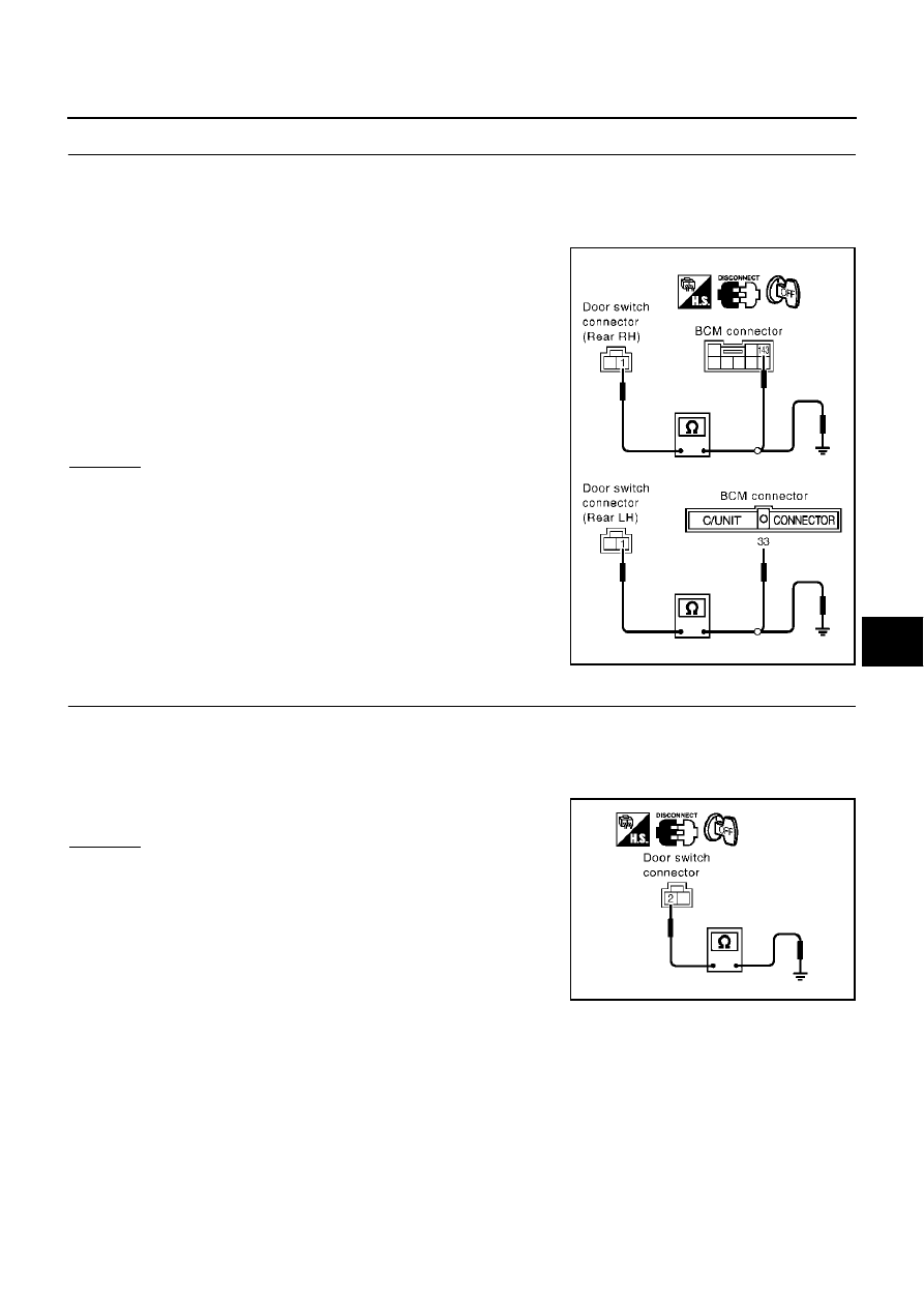
CHECK DOOR SWITCH
1.
Turn ignition switch OFF.
2.
Disconnect door switch and BCM connector.
3.
Check continuity between rear door switch connector D62 (rear LH), D82 (rear RH) terminal 1 (W) and
BCM connector M4 (rear LH), B4 (rear RH) terminal 33 (W), 143 (W/L).
4.
Check continuity between rear door switch connector D62, D82
terminal 1(W) and ground.
OK or NG
OK
>> GO TO 3.
NG
>> Repair or replace harness.
3.
CHECK REAR DOOR SWITCH GROUND CIRCUIT
1.
Turn ignition switch OFF.
2.
Disconnect rear door switch and BCM connector.
3.
Check continuity between rear door switch connector D62 (rear LH), D82 (rear RH) terminal 2 (B) and
ground.
OK or NG
OK
>> GO TO 4.
NG
>> Repair or replace harness.
Rear door switch LH
1 (W) – 33 (W)
: Continuity should exist.
Rear door switch RH
1 (W) – 143 (W/L)
: Continuity should exist.
Each door switch
1 (W) – Ground
: Continuity should not exist.
PIIB0200E
2 (B) – Ground
: Continuity should exist.
PIIB0201E