Infiniti I35 (A33). Manual - part 362


  Index      Infiniti     Infiniti I35 (A33) - service repair manual 2004 year


Search            


Content   ..  360  361  362  363   ..


Infiniti I35 (A33). Manual - part 362


Symptom

Possible cause

Repair order

RH low beam does not operate,
but RH high beam operates.

1. Headlamp RH relay
2. Open in the RH low beam cir-

cuit

3. RH low beam ground circuit
4. Xenon bulb
5. HID control unit

1. Check headlamp RH relay
2. Check harness between headlamp RH relay termi-

nal 7 and headlamp RH for open circuit.

3. Check harness between headlamp RH and ground.
4. Replace the xenon bulb with other side bulb or new

one. (If headlamps illuminate correctly, replace the
bulb.)

5. Replace the HID control unit with other side control

unit or new one. (If headlamps illuminate correctly,
replace the control unit.)

High beam indicator does not work. 1. Bulb

2. Open in high beam indicator

circuit

1. Check bulb in combination meter.
2. Check the following.
a. Harness between headlamp RH relay and combina-

tion meter for an open circuit

b. Harness between high beam indicator and lighting

switch

Exterior lamp battery saver control
does not operate properly.

1. Door switch LH or RH circuit
2. Smart entrance control unit

1. Check the following.
a. Harness between smart entrance control unit and

door switch LH or RH for open or short circuit

b. Door switch LH or RH ground circuit
c. Door switch LH or RH
2. Check smart entrance control unit. (EL-368)

Bulb Replacement

NHEL0259

CAUTION:

I

After replacing a new xenon bulb, be sure to make aiming
adjustments.

I

Hold only the plastic base when handling the bulb. Never
touch the glass envelope.

I

Do not leave headlamp reflector without bulb for a long
period of time. Dust, moisture, smoke, etc. entering head-
lamp body may affect the performance of the headlamp.
Remove headlamp bulb from the headlamp reflector just
before a replacement bulb is installed.

1.

Disconnect negative battery cable.

2.

Disconnect headlamp connector.

3.

Remove headlamp assembly.

WARNING:

Never service a xenon headlamp without disconnecting nega-
tive battery cable and with wet hands.

SEL678W

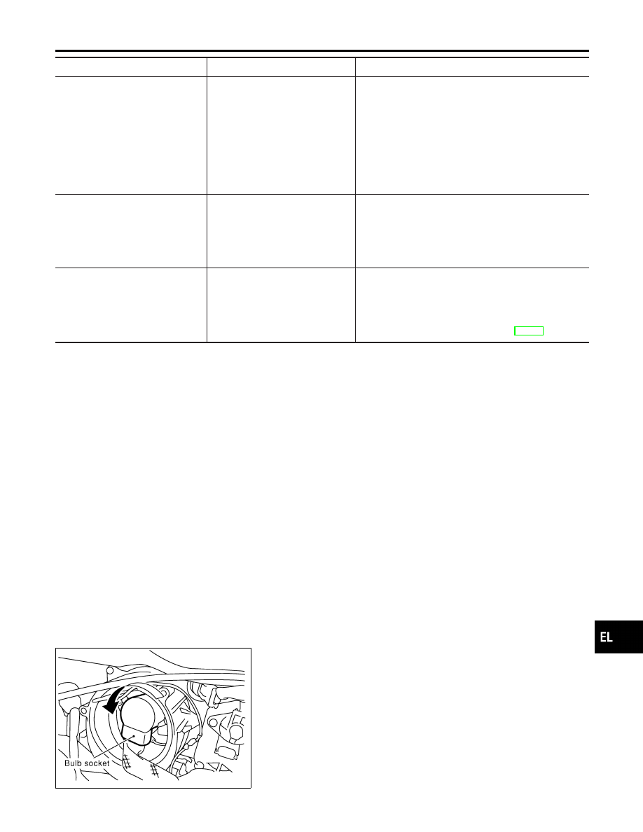
XENON BULB (LOW BEAM)

NHEL0259S01

1.

Remove headlamp seal cover by turning it counterclockwise.

2.

Turn bulb socket counterclockwise with keep pushing, then
remove it.

GI

MA

EM

LC

EC

FE

AT

AX

SU

BR

ST

RS

BT

HA

SC

IDX

HEADLAMP (FOR USA)

Trouble Diagnoses (Cont’d)

EL-49

SEL679W

3.

Release retaining pin.

4.

Remove the xenon bulb.

5.

Install in the reverse order of removal.

CAUTION:

I

When disposing of the xenon bulb, do not break it; always
dispose of it as is.

I

Make sure to install the bulb securely; if the xenon bulb is
improperly installed in its socket, high-tension current
leaks occur. This may lead to a melted bulb and/or bulb
socket.

SEL680W

HIGH BEAM

NHEL0259S02

1.

Turn the bulb clockwise (LH high beam) or counterclockwise
(RH high beam).

2.

Remove the bulb.

3.

Install in the reverse order of removal.

HEADLAMP (FOR USA)

Bulb Replacement (Cont’d)

EL-50

SEL681W

Aiming Adjustment

=NHEL0260

LOW BEAM

NHEL0260S01

1.

Turn headlamp low beam on.

2.

Use adjusting screw to perform aiming adjustment.

I

First tighten the adjusting screw all the way and then
make adjustment by loosening the screw.

SEL957VA

GI

MA

EM

LC

EC

FE

AT

AX

SU

BR

ST

RS

BT

HA

SC

IDX

HEADLAMP (FOR USA)

Aiming Adjustment

EL-51

Component Parts and Harness Connector
Location

NHEL0261

SEL050YA

System Description

NHEL0262

The headlamp system for Canada vehicles contains a daytime light control unit that activates the high beam
headlamps at approximately half illumination whenever the engine is running. If the parking brake is applied
before the engine is started the daytime lights will not be illuminated. The daytime lights will illuminate once
the parking brake is released. Thereafter, the daytime lights will continue to operate when the parking brake
is applied.
And battery saver system is controlled by the smart entrance control unit.
Power is supplied at all times

I

to headlamp LH relay terminals 1 and 6

I

through 20A fuse (No. 54, located in the fuse and fusible link box), and

I

to headlamp RH relay terminals 1 and 6

I

through 20A fuse (No. 55, located in the fuse and fusible link box), and

I

to smart entrance control unit terminal 49

I

through 10A fuse [No. 13, located in the fuse block (J/B)].

Ground is supplied

I

to daytime light control unit terminal 16 and

I

to smart entrance control unit terminals 43 and 64

When the ignition switch is in the ON or START position, power is also supplied

I

to daytime light control unit terminal 3,

I

through 10A fuse [No. 28, located in the fuse block (J/B)], and

I

to smart entrance control unit terminal 27

I

through 10A fuse [No. 10, located in the fuse block (J/B)].

When the ignition switch is in the ACC or ON position, power is supplied

I

to smart entrance control unit terminal 26

I

through 10A fuse [No. 1, located in the fuse block (J/B)].

When the ignition switch is in the START position, power is supplied

I

to daytime light control unit terminal 2

I

through 10A fuse [No. 21, located in the fuse block (J/B)].

HEADLAMP OPERATION

NHEL0262S01

Power Supply to Low Beam and High Beam

NHEL0262S0101

When lighting switch is in 2ND or PASS position, ground is supplied

HEADLAMP (FOR CANADA) — DAYTIME LIGHT SYSTEM —

Component Parts and Harness Connector Location

EL-52


Content   ..  360  361  362  363   ..