Infiniti I35 (A33). Manual - part 361
SEL545Y
GI
MA
EM
LC
EC
FE
AT
AX
SU
BR
ST
RS
BT
HA
SC
IDX
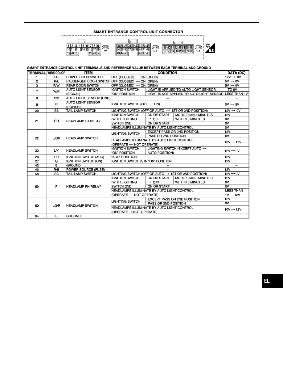
HEADLAMP (FOR USA)
Wiring Diagram — H/LAMP — (Cont’d)
EL-45
|
|
|
SEL545Y GI MA EM LC EC FE AT AX SU BR ST RS BT HA SC IDX HEADLAMP (FOR USA) Wiring Diagram — H/LAMP — (Cont’d) EL-45 |