Infiniti I35 (A33). Manual - part 329
PBIB1741E
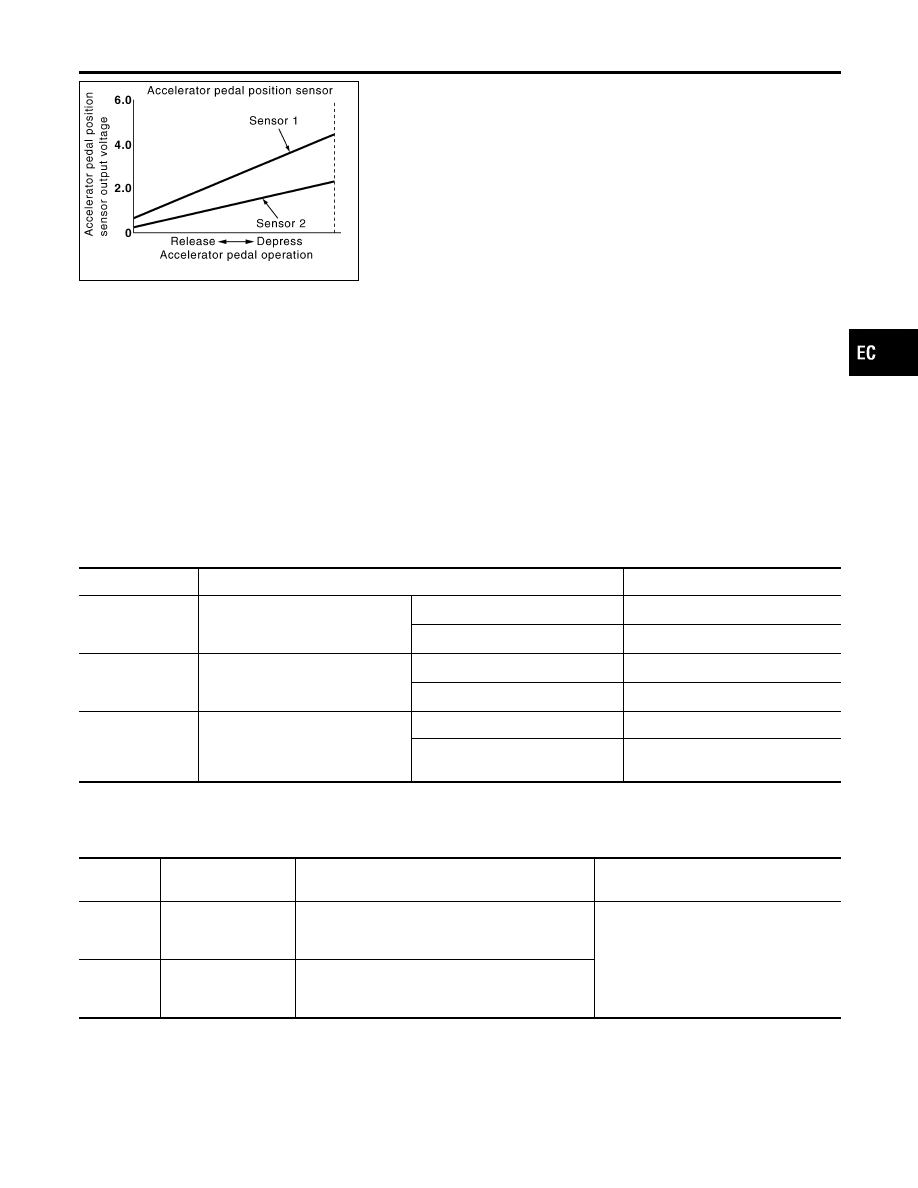
Component Description
NHEC1347
The accelerator pedal position sensor is installed on the upper end
of the accelerator pedal assembly. The sensor detects the accel-
erator position and sends a signal to the ECM.
Accelerator pedal position sensor has two sensors. These sensors
are a kind of potentiometers which transform the accelerator pedal
position into output voltage, and emit the voltage signal to the ECM.
In addition, these sensors detect the opening and closing speed of
the accelerator pedal and feed the voltage signals to the ECM. The
ECM judges the current opening angle of the accelerator pedal
from these signals and controls the throttle control motor based on
these signals.
Idle position of the accelerator pedal is determined by the ECM
receiving the signal from the accelerator pedal position sensor. The
ECM uses this signal for the engine operation such as fuel cut.
CONSULT-II Reference Value in Data Monitor
Mode
NHEC1348
Specification data are reference values.
MONITOR ITEM
CONDITION
SPECIFICATION
ACCEL SEN1
I
Ignition switch: ON (engine
stopped)
I
Shift lever: D
Accelerator pedal: Released
0.41 - 0.71V
Accelerator pedal: Fully depressed
More than 3.7V
ACCEL SEN2*
I
Ignition switch: ON (engine
stopped)
I
Shift lever: D
Accelerator pedal: Released
0.15 - 0.97V
Accelerator pedal: Fully depressed
More than 3.5V
CLSD THL POS
I
Ignition switch: ON
(engine stopped)
I
Shift lever: D
Accelerator pedal: Released
ON
Accelerator pedal: Slightly
depressed
OFF
*: Accelerator pedal position sensor 2 signal is converted by ECM internally. Thus, it differs from ECM terminal voltage signal.
On Board Diagnosis Logic
NHEC1457
These self-diagnoses have the one trip detection logic.
DTC No.
Trouble diagnosis
name
DTC Detecting Condition
Possible Cause
P2127
2127
Accelerator pedal
position sensor 2 cir-
cuit low input
An excessively low voltage from the APP sensor 2
is sent to ECM.
I
Harness or connectors
(The APP sensor 2 circuit is open or
shorted.)
I
Accelerator pedal position sensor
(Accelerator pedal position sensor 2)
P2128
2128
Accelerator pedal
position sensor 2 cir-
cuit high input
An excessively high voltage from the APP sensor
2 is sent to ECM.
GI
MA
EM
LC
FE
AT
AX
SU
BR
ST
RS
BT
HA
SC
EL
IDX
DTC P2127, P2128 APP SENSOR
Component Description
EC-657