Infiniti I35 (A33). Manual - part 301
Description
NHEC1089
SYSTEM DESCRIPTION
NHEC1089S01
Sensor
Input Signal to ECM
ECM
function
Actuator
Crankshaft position sensor (POS)
Camshaft position sensor (PHASE)
Engine speed
EVAP can-
ister purge
flow control
EVAP canister purge volume
control solenoid valve
Mass air flow sensor
Amount of intake air
Engine coolant temperature sensor
Engine coolant temperature
Ignition switch
Start signal
Throttle position sensor
Throttle position
Accelerator pedal position sensor
Accelerator pedal position
Heated oxygen sensor 1
Density of oxygen in exhaust gas
(Mixture ratio feedback signal)
Fuel tank temperature sensor
Fuel temperature in fuel tank
Vehicle speed sensor
Vehicle speed
This system controls flow rate of fuel vapor from the EVAP canis-
ter. The opening of the vapor by-pass passage in the EVAP canis-
ter purge volume control solenoid valve changes to control the flow
rate. The EVAP canister purge volume control solenoid valve
repeats ON/OFF operation according to the signal sent from the
ECM. The opening of the valve varies for optimum engine control.
The optimum value stored in the ECM is determined by consider-
ing various engine conditions. When the engine is operating, the
flow rate of fuel vapor from the EVAP canister is regulated as the
air flow changes.
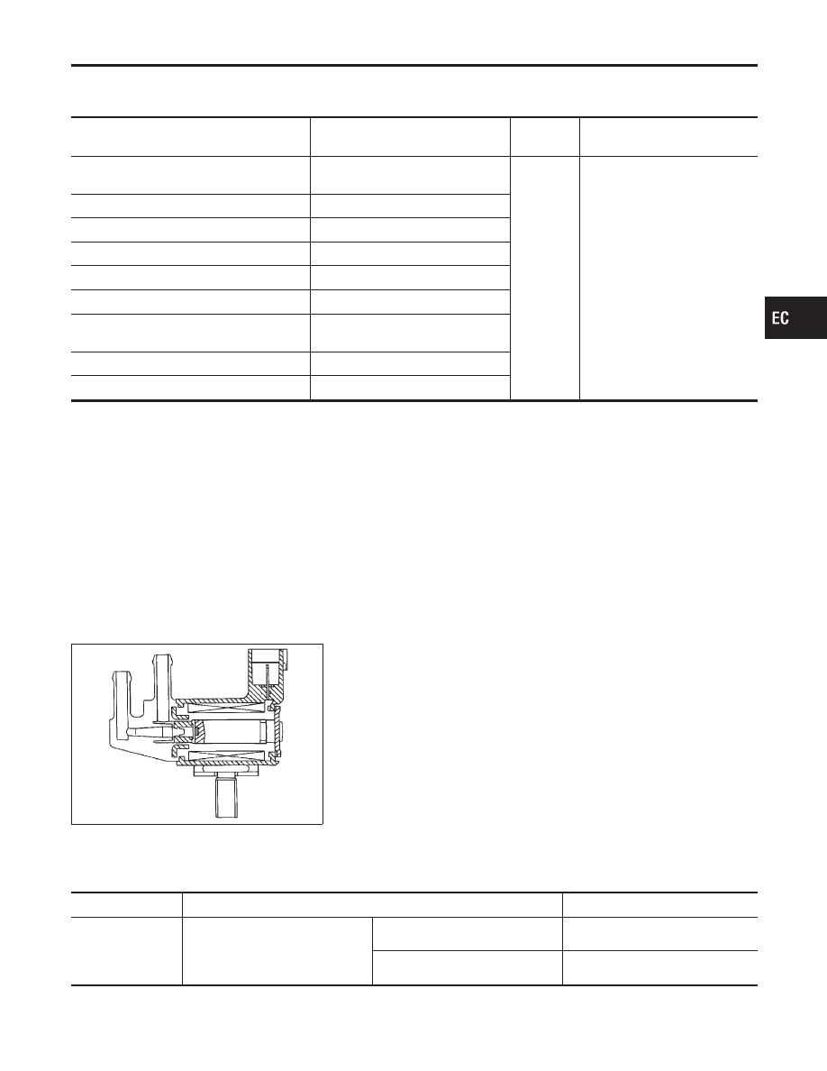
SEF337U
COMPONENT DESCRIPTION
NHEC1089S02
The EVAP canister purge volume control solenoid valve uses a
ON/OFF duty to control the flow rate of fuel vapor from the EVAP
canister. The EVAP canister purge volume control solenoid valve
is moved by ON/OFF pulses from the ECM. The longer the ON
pulse, the greater the amount of fuel vapor that will flow through the
valve.
CONSULT-II Reference Value in Data Monitor
Mode
NHEC1090
Specification data are reference values.
MONITOR ITEM
CONDITION
SPECIFICATION
PURG VOL C/V
I
Engine: After warming up
I
Air conditioner switch OFF
I
Shift lever: N
I
No-load
Idle (Vehicle stopped)
0%
2,000 rpm
—
GI
MA
EM
LC
FE
AT
AX
SU
BR
ST
RS
BT
HA
SC
EL
IDX
DTC P1444 EVAP CANISTER PURGE VOLUME CONTROL SOLENOID VALVE
Description
EC-545