Infiniti I35 (A33). Manual - part 291
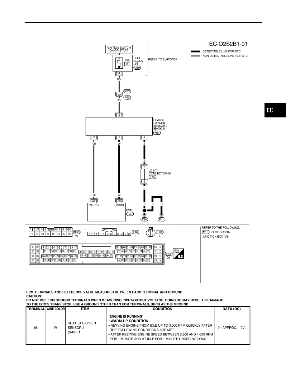
Wiring Diagram
=NHEC1175
BANK 1
NHEC1175S01
MEC541D
SEC661DC
GI
MA
EM
LC
FE
AT
AX
SU
BR
ST
RS
BT
HA
SC
EL
IDX
DTC P1147, P1167 HO2S2
Wiring Diagram
EC-505
|
|
|
Wiring Diagram =NHEC1175 BANK 1 NHEC1175S01 MEC541D SEC661DC GI MA EM LC FE AT AX SU BR ST RS BT HA SC EL IDX DTC P1147, P1167 HO2S2 Wiring Diagram EC-505 |