Infiniti I35 (A33). Manual - part 269


  Index      Infiniti     Infiniti I35 (A33) - service repair manual 2004 year


Search            


Content   ..  267  268  269  270   ..


Infiniti I35 (A33). Manual - part 269


21

CLEAN EVAP PURGE LINE

Clean EVAP purge line (pipe and rubber tube) using air blower.

©

GO TO 22.

22

CHECK REFUELING EVAP VAPOR LINE

Check refueling EVAP vapor line between EVAP canister and fuel tank for clogging, kink, looseness and improper connec-
tion. For location, refer to “EVAPORATIVE EMISSION LINE DRAWING”, EC-41.

OK or NG

OK

©

GO TO 23.

NG

©

Repair or replace hoses and tubes.

23

CHECK SIGNAL LINE AND RECIRCULATION LINE

Check signal line and recirculation line between filler neck tube and fuel tank for clogging, kink, cracks, looseness and
improper connection.

OK or NG

OK

©

GO TO 24.

NG

©

Repair or replace hoses, tubes or filler neck tube.
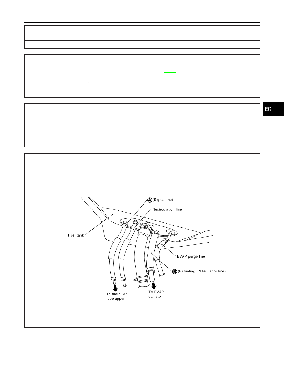
24

CHECK REFUELING CONTROL VALVE

1. Remove fuel filler cap.
2. Check air continuity between hose ends A and B.

Blow air into hose end B. Air should flow freely into the fuel tank.

3. Blow air into hose end A and check that there is no leakage.
4. Apply pressure to both hose ends A and B [20 kPa (150 mmHg, 5.91 inHg)] using a pressure pump and a suitable

3-way connector. Check that there is no leakage.

SEF830X

OK or NG

OK

©

GO TO 25.

NG

©

Replace or refueling control valve with fuel tank.

GI

MA

EM

LC

FE

AT

AX

SU

BR

ST

RS

BT

HA

SC

EL

IDX

DTC P0456 EVAP CONTROL SYSTEM

Diagnostic Procedure (Cont’d)

EC-417

25

CHECK FUEL LEVEL SENSOR

Refer to EL-140, “Fuel Level Sensor Unit Check”.

OK or NG

OK

©

GO TO 26.

NG

©

Replace fuel level sensor unit.

26

CHECK INTERMITTENT INCIDENT

Refer to “TROUBLE DIAGNOSIS FOR INTERMITTENT INCIDENT”, EC-152.

©

INSPECTION END

DTC P0456 EVAP CONTROL SYSTEM

Diagnostic Procedure (Cont’d)

EC-418

SEC088D

Component Description

NHEC0991

The fuel level sensor is mounted in the fuel level sensor unit. The
sensor detects a fuel level in the fuel tank and transmits a signal
to the ECM.
It consists of two parts, one is mechanical float and the other is
variable resistor. Fuel level sensor output voltage changes depend-
ing on the movement of the fuel mechanical float.

On Board Diagnostic Logic

NHEC0992

When the vehicle is parked, naturally the fuel level in the fuel tank
is stable. It means that output signal of the fuel level sensor does
not change. If ECM senses sloshing signal from the sensor, fuel
level sensor malfunction is detected.

DTC No.

Trouble diagnosis

name

DTC Detecting Condition

Possible Cause

P0460
0460

Fuel level sensor cir-
cuit noise

Even though the vehicle is parked, a signal being
varied is sent from the fuel level sensor to ECM.

I

Fuel level sensor circuit
(The fuel level sensor circuit is open
or shorted.)

I

Fuel level sensor

SEF195Y

DTC Confirmation Procedure

NHEC0993

NOTE:
If DTC Confirmation Procedure has been previously conducted,
always turn ignition switch OFF and wait at least 10 seconds before
conducting the next test.

WITH CONSULT-II

NHEC0993S01

1)

Turn ignition switch ON.

2)

Select “DATA MONITOR” mode with CONSULT-II.

3)

Start engine and wait maximum of 2 consecutive minutes.

4)

If 1st trip DTC is detected, go to “Diagnostic Procedure”,
EC-421.

WITH GST

NHEC0993S02

Follow the procedure “WITH CONSULT-II” above.

GI

MA

EM

LC

FE

AT

AX

SU

BR

ST

RS

BT

HA

SC

EL

IDX

DTC P0460 FUEL LEVEL SENSOR

Component Description

EC-419

Wiring Diagram

NHEC0994

MEC637E

SEF711YB

DTC P0460 FUEL LEVEL SENSOR

Wiring Diagram

EC-420


Content   ..  267  268  269  270   ..