Infiniti I35 (A33). Manual - part 261


  Index      Infiniti     Infiniti I35 (A33) - service repair manual 2004 year


Search            


Content   ..  259  260  261  262   ..


Infiniti I35 (A33). Manual - part 261


Diagnostic Procedure

NHEC0983

1

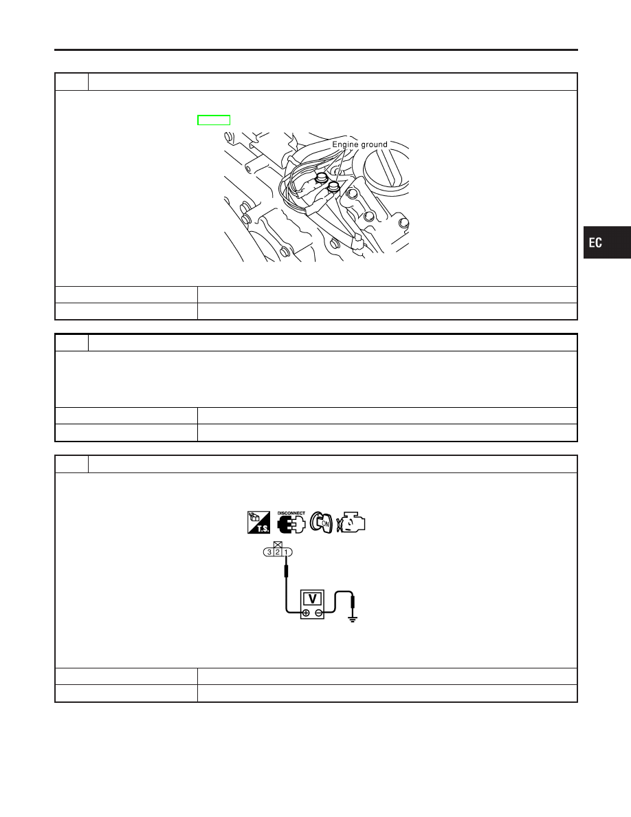
CHECK GROUND CONNECTIONS

1. Turn ignition switch OFF.
2. Loosen and retighten two engine ground screws.

Refer to “Ground Inspection”, EC-160.

SEC047D

OK or NG

OK

©

GO TO 2.

NG

©

Repair or replace ground connections.

2

CHECK CONNECTOR

1. Disconnect EVAP control system pressure sensor harness connector.
2. Check sensor harness connector for water.

Water should not exist.

OK or NG

OK

©

GO TO 3.

NG

©

Repair or replace harness connector.

3

CHECK EVAP CONTROL SYSTEM PRESSURE SENSOR POWER SUPPLY CIRCUIT

1. Turn ignition switch ON.
2. Check voltage between EVAP control system pressure sensor terminal 1 and ground with CONSULT-II or tester.

SEC063D

Voltage: Approximately 5V

OK or NG

OK

©

GO TO 5.

NG

©

GO TO 4.

GI

MA

EM

LC

FE

AT

AX

SU

BR

ST

RS

BT

HA

SC

EL

IDX

DTC P0453 EVAP SYSTEM PRESSURE SENSOR

Diagnostic Procedure

EC-385

4

DETECT MALFUNCTIONING PART

Check the following.

I

Harness connectors B2, M2

I

Harness connectors M81, F49

I

Harness for open or short between EVAP control system pressure sensor and ECM

©

Repair harness or connectors.

5

CHECK EVAP CONTROL SYSTEM PRESSURE SENSOR GROUND CIRCUIT FOR OPEN AND SHORT

1. Turn ignition switch OFF.
2. Disconnect ECM harness connector.
3. Disconnect TCM harness connector.
4. Check harness continuity between EVAP control system pressure sensor terminal 3 and ECM terminal 58, TCM termi-

nal 42.
Refer to Wiring Diagram.

Continuity should exist.

5. Also check harness for short to power.

OK or NG

OK

©

GO TO 7.

NG

©

GO TO 6.

6

DETECT MALFUNCTIONING PART

Check the following.

I

Harness connectors B2, M2

I

Harness connectors M81, F49

I

Joint connector-20

I

Harness for open between EVAP control system pressure sensor and ECM

I

Harness for open between EVAP control system pressure sensor and TCM (Transmission Control Module)

©

Repair open circuit or short to power in harness or connectors.

7

CHECK EVAP CONTROL SYSTEM PRESSURE SENSOR INPUT SIGNAL CIRCUIT FOR OPEN AND
SHORT

1. Check harness continuity between ECM terminal 60 and EVAP control system pressure sensor terminal 2.

Refer to Wiring Diagram.

Continuity should exist.

2. Also check harness for short to ground and short to power.

OK or NG

OK

©

GO TO 9.

NG

©

GO TO 8.

8

DETECT MALFUNCTIONING PART

Check the following.

I

Harness connectors B2, M2

I

Harness connectors M81, F49

I

Harness for open or short between ECM and EVAP control system pressure sensor

©

Repair open circuit or short to ground or short to power in harness or connectors.

DTC P0453 EVAP SYSTEM PRESSURE SENSOR

Diagnostic Procedure (Cont’d)

EC-386

9

CHECK RUBBER TUBE FOR CLOGGING

1. Disconnect rubber tube connected to EVAP canister vent control valve.
2. Check the rubber tube for clogging.

OK or NG

OK

©

GO TO 10.

NG

©

Clean the rubber tube using an air blower.

10

CHECK EVAP CANISTER VENT CONTROL VALVE-I

1. Remove EVAP canister vent control valve from EVAP canister.
2. Check portion of EVAP canister vent control valve for being rusted.

SEF376Z

OK or NG

OK

©

GO TO 11.

NG

©

Replace EVAP canister vent control valve.

GI

MA

EM

LC

FE

AT

AX

SU

BR

ST

RS

BT

HA

SC

EL

IDX

DTC P0453 EVAP SYSTEM PRESSURE SENSOR

Diagnostic Procedure (Cont’d)

EC-387

11

CHECK EVAP CANISTER VENT CONTROL VALVE

With CONSULT-II

1. Perform “VENT CONTROL/V” in “ACTIVE TEST” mode.
2. Check air passage continuity and operation delay time under the following conditions.

SEC158D

Without CONSULT-II

Check air passage continuity and operation delay time under the following conditions.

SEF378Z

Make sure new O-ring is installed properly.

OK or NG

OK

©

GO TO 13.

NG

©

GO TO 12.

12

CHECK EVAP CANISTER VENT CONTROL VALVE-III

1. Clean the air passage (portion to B) of EVAP canister vent control valve using an air blower.
2. Perform Test No. 14 again.

OK or NG

OK

©

GO TO 13.

NG

©

Replace EVAP canister vent control valve.

DTC P0453 EVAP SYSTEM PRESSURE SENSOR

Diagnostic Procedure (Cont’d)

EC-388


Content   ..  259  260  261  262   ..