Infiniti I35 (A33). Manual - part 113


  Index      Infiniti     Infiniti I35 (A33) - service repair manual 2004 year


Search            


Content   ..  111  112  113  114   ..


Infiniti I35 (A33). Manual - part 113


TCS (Traction Control System) Operation

=NHBR0145

I

This system is designed to limit wheel slip during acceleration by cutting fuel to selected cylinders and
changing transmission shift schedule.
The ABS/TCS control unit monitors wheel speed slips through the ABS wheel sensors and determines the
desired torque reduction needed to minimize wheel spin.
The torque reduction by the ABS/TCS control unit may result in a combination of fuel cutoff, throttle control,
and change shift timing of the transmission.
The torque reduction is sent from the ABS/TCS control unit through the data link to the ECM and TCM.
The ECM will cut off fuel and/or close throttle valve little bit, and/or TCM change shift schedule to achieve
torque reduction.
The TCS will be enabled when the TCS switch is in the ON position (TCS OFF indicator not illuminated),
and if the catalytic converter temperature is within normal operating range.

I

This system has a self-diagnostic function. When the ignition switch is initially turned “ON”, the SLIP indi-
cator lamp and TCS OFF indicator lamp light. If there is no problem with the ABS and TCS, both indica-
tor lamps will go out as soon as the engine starts.

I

The TCS OFF switch cancels the TCS function. The TCS OFF indicator lamp then lights to indicate that
the TCS is not operating.

I

This system utilizes a fuel-cut function to control drive torque. If fuel cut continues for an extended period
of time during high-speed operations, the catalyst may melt and deteriorate. During continued TCS
operations, the system will sometimes suspend the drive torque control function, preventing catalyst melt-
ing and deterioration.
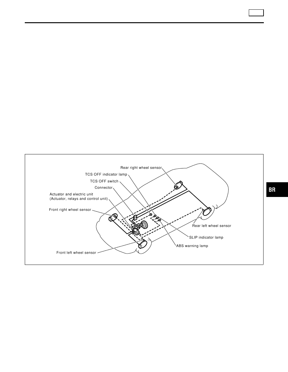
System Components

NHBR0146

SBR039F

GI

MA

EM

LC

EC

FE

AT

AX

SU

ST

RS

BT

HA

SC

EL

IDX

DESCRIPTION

TCS

TCS (Traction Control System) Operation

BR-37

SFIA0289E

SFIA0290E

System Description

NHBR0147

SENSOR

NHBR0147S01

The front sensor units consist of a gear-shaped sensor rotor and a
sensor element. the element contains a magnet and IC. The front
wheel sensors are installed on the front of the wheel knuckles. As
the wheel rotates, the sensor generates a square-wave signal. The
frequency increase as the wheel speed increases.

SBR655E

CONTROL UNIT

NHBR0147S02

ABS Function

NHBR0147S0201

The control unit computes the wheel rotating speed by the signal
current sent from the sensor. Then it supplies a DC current to the
actuator solenoid valve. It also controls ON-OFF operation of the
valve relay and motor relay. If any electrical malfunction should be
detected in the system, the warning lamp is turned on. In this
condition, the ABS will be deactivated, and the vehicle’s brake
system reverts to normal operation.

TCS Function

NHBR0147S0202

Drive wheel slippage is detected by the 4-wheel rotating speed
signal. When the wheel slip becomes excessive, the TCS operates,
causing the SLIP indicator lamp to flash. And, at the same time,
fuel-cut and throttle opening signals are sent to the ECM and a
signal requiring a change in the shift schedule is sent to the TCM.
When the TCS OFF switch is used to cancel TCS function, the TCS
OFF indicator lamp will light. (TCS does not activate.) In case of a
malfunction in the TCS, both the SLIP indicator lamp and the TCS
OFF indicator lamp will light, while shutting down the TCS system
operation. The vehicle will operate in the same way as a vehicle
not equipped with the TCS.

SBR645EB

ACTUATOR

NHBR0147S03

The actuator contains:

I

An electric motor and pump

I

Two relays

I

Eight solenoid valves, each inlet and outlet for
— LH front
— RH front
— LH rear
— RH rear

DESCRIPTION

TCS

System Description

BR-38

These components control the hydraulic circuit. The ABS control
unit directs the actuator to increase, hold or decrease hydraulic
pressure to all or individual wheels.

ABS Actuator Operation

NHBR0147S0301

Inlet solenoid
valve

Outlet solenoid
valve

Normal brake operation

OFF (Open)

OFF (Closed)

Master cylinder brake fluid pressure is directly trans-
mitted to caliper via the inlet solenoid valve.

ABS operation

Pressure hold

ON (Closed)

OFF (Closed)

Hydraulic circuit is shut off to hold the caliper brake
fluid pressure.

Pressure
decrease

ON (Closed)

ON (Open)

Caliper brake fluid is sent to reservoir via the outlet
solenoid valve. Then it is pushed up to the master
cylinder by pump.

Pressure
increase

OFF (Open)

OFF (Closed)

Master cylinder brake fluid pressure is transmitted to
caliper.

GI

MA

EM

LC

EC

FE

AT

AX

SU

ST

RS

BT

HA

SC

EL

IDX

DESCRIPTION

TCS

System Description (Cont’d)

BR-39

Component Parts and Harness Connector
Location

NHBR0053

SBR153F

DESCRIPTION

TCS

Component Parts and Harness Connector Location

BR-40


Content   ..  111  112  113  114   ..