Infiniti I35 (A33). Manual - part 111
SBR868C
SBR646
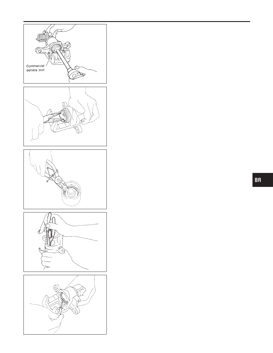
Disassembly
NHBR0040
1.
Remove piston by turning it counterclockwise with suitable
commercial service tool or long nose pliers.
SBR889
2.
Pry off ring A from piston with suitable pliers and remove
adjusting nut.
SBR088B
3.
Disassemble cylinder body.
a.
Pry off ring B with suitable pliers, then remove spring cover,
spring and seat.
b.
Pry off ring C, then remove key plate, push rod and rod.
SBR656
c.
Remove piston seal.
Be careful not to damage cylinder body.
GI
MA
EM
LC
EC
FE
AT
AX
SU
ST
RS
BT
HA
SC
EL
IDX
REAR DISC BRAKE
Disassembly
BR-29