Infiniti G37 Coupe. Manual - part 282
BRC-102
< ON-VEHICLE REPAIR >
[VDC/TCS/ABS]
ABS ACTUATOR AND ELECTRIC UNIT (CONTROL UNIT)
ABS ACTUATOR AND ELECTRIC UNIT (CONTROL UNIT)
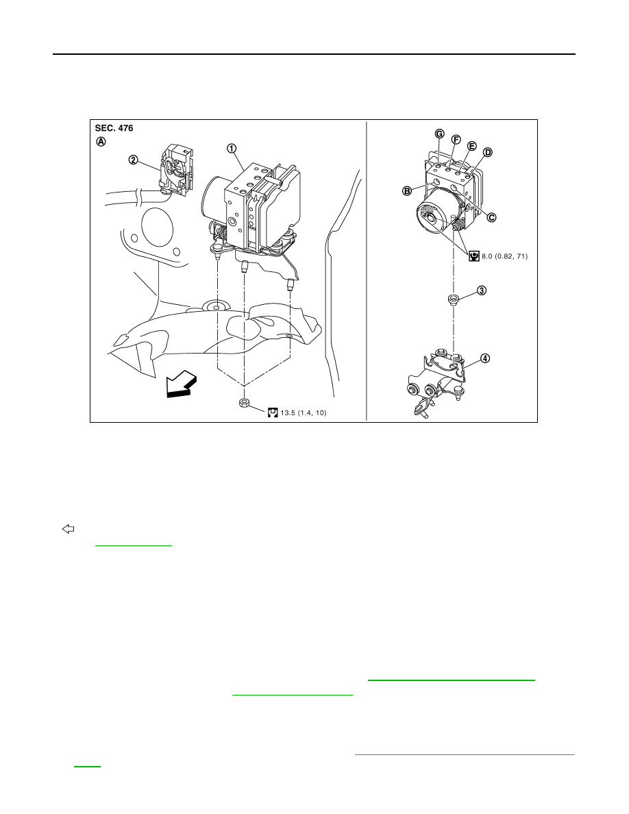
Exploded View
INFOID:0000000001635167
Removal and Installation
INFOID:0000000001635168
REMOVAL
CAUTION:
• Before servicing, disconnect the battery cable from negative terminal.
• To remove brake tube, use a flare nut wrench to prevent flare nuts and brake tube from being dam-
aged. To install, use flare nut crowfoot and torque wrench.
• Do not apply excessive impact to ABS actuator and electric unit (control unit), such as dropping it.
• Do not remove and install actuator by holding harness.
• After work is completed, bleed air from brake tube. Refer to
BR-12, "Bleeding Brake System"
1.
Remove cowl top cover. Refer to
.
2.
Disconnect ABS actuator and electric unit (control unit) connector.
3.
Loosen brake tube flare nuts, then remove brake tubes from ABS actuator and electric unit (control unit).
4.
Remove tire (front LH side).
5.
Remove fender protector (rear): (front LH side). Refer to
EXT-24, "FENDER PROTECTOR : Exploded
.
6.
Remove ABS actuator and electric unit (control unit) bracket mounting nut.
1.
ABS actuator and electric unit (control
unit)
2.
Connector
3.
Bushing
4.
Bracket
A.
Left side of dash panel
B.
From master cylinder secondary side C.
From master cylinder primary side
D.
To front LH brake caliper
E.
To rear RH brake caliper
F.
To Rear LH brake caliper
G.
To front RH brake caliper
: Vehicle front
Refer to
for symbol marks in the figure.
JSFIA0007GB