Infiniti G37 Coupe. Manual - part 281


  Index      Infiniti     Infiniti G37 Coupe - service repair manual 2008 year


Search            


Content   ..  279  280  281  282   ..


Infiniti G37 Coupe. Manual - part 281


BRC-98

< PRECAUTION >

[VDC/TCS/ABS]

PRECAUTIONS

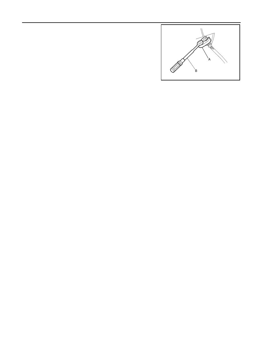
• Tighten the brake tube flare nut to the specified torque with a crow-

foot (A) and torque wrench (B).

• Always conform the specified tightening torque when installing the

brake pipes.

• Brake system is an important safety part. If a brake fluid leak is

detected, always disassemble the affected part. If a malfunction is
detected, replace part with a new one.

• Turn the ignition switch OFF and disconnect the ABS actuator and

electric unit (control unit) connector or the battery negative terminal
before performing the work.

Precaution for Brake Control

INFOID:0000000001635158

• When starting engine or when starting vehicle just after starting engine, brake pedal may vibrate or motor

operating noise may be heard from engine compartment. This is normal condition.

• When an error is indicated by ABS or another warning lamp, collect all necessary information from customer

(what symptoms are present under what conditions) and check for estimate causes before starting diagnos-
tic servicing. Besides electrical system inspection, check brake booster operation, brake fluid level, and oil
leaks.

• If tire size and type are used in an improper combination, or brake pads are not Genuine NISSAN parts,

stopping distance or steering stability may deteriorate.

• ABS might be out of order or malfunctions by putting a radio (wiring inclusive), an antenna and a lead-in wire

near the control unit.

• If aftermarket parts (car stereo, CD player, etc.) have been installed, check for incidents such as harness

pinches, open circuits, and improper wiring.

• VDC system may not operate normally or a VDC OFF indicator lamp or SLIP indicator lamp may light. 
- When replacing the following parts with parts other than genuine parts or making modifications: Suspension

related parts (shock absorber, spring, bushing, etc.), tires, wheels (other than specified sizes), brake-related
parts (pad, rotor, caliper, etc.), engine-related parts (muffler, ECM, etc.) and body reinforcement-related parts
(roll bar, tower bar, etc.).

- When driving with worn or deteriorated suspension, tires and brake-related parts.

JPFIA0001ZZ

PREPARATION

BRC-99

< PREPARATION >

[VDC/TCS/ABS]

C

D

E

G

H

I

J

K

L

M

A

B

BRC

N

O

P

PREPARATION

PREPARATION

Special Service Tool

INFOID:0000000001635159

The actual shapes of Kent-Moore tools may differ from those of special service tools illustrated here.

Commercial Service Tool

INFOID:0000000001635160

Tool number
(Kent-Moore No.)
Tool name

Description

ST30720000
(J-25405)
Drift
a: 77 mm (3.03 in) dia.
b: 55.5 mm (2.185 in) dia.

Installing rear sensor rotor

ST27863000
(

)

Drift
a: 74.5 mm (2.933 in) dia. 
b: 62.5 mm (2.461 in) dia. 

KV40104710
(

)

a: 76.3 mm (3.004 in) dia.
b: 67.9 mm (2.673 in) dia.

ZZA0701D

ZZA0832D

ZZA0832D

Tool name

Description

1. Flare nut crowfoot
 a: 10 mm (0.39 in) /12 mm (0.47 in)
2. Torque wrench

Installing brake tube

S-NT360

BRC-100

< ON-VEHICLE REPAIR >

[VDC/TCS/ABS]

WHEEL SENSOR

ON-VEHICLE REPAIR

WHEEL SENSOR

Exploded View

INFOID:0000000001635161

NOTE:
The above figure (front side) shows left side. Right side is the mirror image.

Removal and Installation

INFOID:0000000001635162

REMOVAL

Pay attention to the following when removing sensor.

CAUTION:

• Do not twist sensor harness as much as possible, when removing it. Pull sensors out without pulling

sensor harness.

• Take care to avoid damaging sensor edges or rotor teeth. Remove wheel sensor first before remov-

ing front or rear wheel hub. This is to avoid damage to sensor wiring and loss of sensor function.

INSTALLATION

Pay attention to the following when installing wheel sensor. Tighten installation bolts to the specified torques.
• When installing, make sure there is no foreign material such as iron chips on and in the mounting hole of the

wheel sensor. Make sure no foreign material has been caught in the sensor rotor. Remove any foreign mate-
rial and clean the mount.

• When installing wheel sensor, be sure to press rubber grommets in until they lock at locations shown above

in the figure. When installed, harness must not be twisted.

1.

Front LH wheel sensor

2.

Rear LH wheel sensor

3.

Rear RH wheel sensor

A.

Front

B.

Rear

: Vehicle front

Refer to 

GI-4, "Components"

 for symbol marks in the figure.

JSFIA0001GB

SENSOR ROTOR

BRC-101

< ON-VEHICLE REPAIR >

[VDC/TCS/ABS]

C

D

E

G

H

I

J

K

L

M

A

B

BRC

N

O

P

SENSOR ROTOR

FRONT SENSOR ROTOR

FRONT SENSOR ROTOR : Exploded View

INFOID:0000000001635163

Refer to 

FAX-5, "Exploded View"

.

FRONT SENSOR ROTOR : Removal and Installation

INFOID:0000000001635164

REMOVAL

Sensor rotor cannot be disassembled. Remove the sensor rotor together with hub bearing assembly. Refer to

FAX-5, "Exploded View"

.

INSTALLATION

Sensor rotor cannot be disassembled. Remove the sensor rotor together with hub bearing assembly. Refer to

FAX-5, "Exploded View"

.

REAR SENSOR ROTOR

REAR SENSOR ROTOR : Exploded View

INFOID:0000000001635165

REAR SENSOR ROTOR : Removal and Installation

INFOID:0000000001635166

REMOVAL

• Follow the procedure below to remove rear sensor rotor.
- Remove side flange. Refer to 

RAX-10, "Exploded View"

.

- Using a bearing replacer (suitable tool) and puller (suitable tool), remove sensor rotor from side flange.

INSTALLATION

CAUTION:

Do not reuse sensor rotor.
• Follow the procedure below to install rear sensor rotor.
- Using a drifts, press rear sensor rotor onto side flange.

- Install side flange. Refer to 

RAX-10, "Exploded View"

.

1.

Side flange

2.

Rear wheel sensor rotor

Refer to 

GI-4, "Components"

 for symbol marks in the figure.

JSFIA0054JP

A: Drift [SST: ST30720000 (J-25405)]

B: Drift [SST: ST27863000 (

)]

C: Drift [SST: KV40104710 (

)]

SFIA3387E


Content   ..  279  280  281  282   ..