Infiniti G37 Coupe. Manual - part 1284


  Index      Infiniti     Infiniti G37 Coupe - service repair manual 2008 year


Search            


Content   ..  1282  1283  1284  1285   ..


Infiniti G37 Coupe. Manual - part 1284


B TERMINAL CIRCUIT

STR-7

< COMPONENT DIAGNOSIS >

C

D

E

F

G

H

I

J

K

L

M

A

STR

N

P

O

COMPONENT DIAGNOSIS

B TERMINAL CIRCUIT

Description

INFOID:0000000001665981

The “B” terminal is constantly supplied with battery power.

Diagnosis Procedure

INFOID:0000000001665982

CAUTION:

Perform diagnosis under the condition that engine cannot start by the following procedure.
1.

Remove fuel pump fuse.

2.

Crank or start the engine (where possible) until the fuel pressure is released.

1.

CHECK “B” TERMINAL CIRCUIT

1.

Turn ignition switch OFF.

2.

Check that starter motor “B” terminal connection is clean and tight.

3.

Check voltage between starter motor “B” terminal and ground.

Is the inspection result normal?

YES

>> GO TO 2.

NO

>> Check harness between battery and starter motor for open circuit.

2.

CHECK BATTERY CABLE CONNECTION STATUS (VOLTAGE DROP TEST)

1.

Shift A/T selector lever to “P” or “N” position. (A/T models)
Keep depressing clutch pedal fully. (M/T models)

2.

Check voltage between battery positive terminal and starter motor “B” terminal.

Is the inspection result normal?

YES

>> GO TO 3.

NO

>> Check harness between the battery and the starter motor for poor continuity.

3.

CHECK GROUND CIRCUIT STATUS (VOLTAGE DROP TEST)

1.

Shift A/T selector lever to “P” or “N” position. (A/T models)
Keep depressing clutch pedal fully. (M/T models)

2.

Check voltage between starter motor case and battery negative terminal.

Is the inspection result normal?

YES

>> “B” terminal circuit is OK. Further inspection is necessary. Refer to 

STR-2, "Work Flow"

.

NO

>> Check the starter motor case and ground for poor continuity.
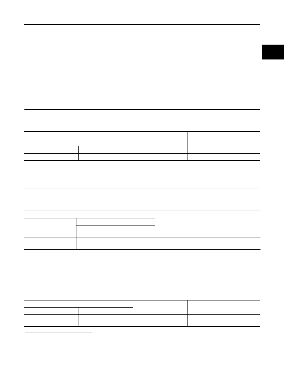
Terminals

Voltage (Approx.)

(+)

(–)

Starter motor “B” terminal

Terminal

E204

2 Ground

Battery 

voltage

Terminals

Condition

Voltage (Approx.)

(+)

(–)

Starter motor

“B” terminal

Terminal

Battery positive terminal

E204

When the ignition switch is 

in START position

Less than

 0.5 V

Terminals

Condition

Voltage (Approx.)

(+)

(–)

Starter motor case

Battery negative terminal

When the ignition switch is in 

START position

Less than 0.2 V

STR-8

< COMPONENT DIAGNOSIS >

S CONNECTOR CIRCUIT

S CONNECTOR CIRCUIT

Description

INFOID:0000000001665983

The starter motor magnetic switch is supplied with power when the ignition switch is turned to the START posi-
tion while the selector lever is in the P or N position for A/T models or the clutch pedal is depressed for M/T
models.

Diagnosis Procedure

INFOID:0000000001665984

CAUTION:

Perform diagnosis under the condition that engine cannot start by the following procedure.
1.

Remove fuel pump fuse.

2.

Crank or start the engine (where possible) until the fuel pressure is released.

1.

CHECK “S” CONNECTOR CIRCUIT

1.

Turn ignition switch OFF.

2.

Disconnect starter motor connector.

3.

Shift A/T selector lever to “P” or “N” position. (A/T models)
Keep depressing clutch pedal fully. (M/T models)

4.

Check voltage between starter motor harness connector and ground.

Is the inspection result normal?

YES

>> “S” connector circuit is OK. Further inspection is necessary. Refer to 

STR-2, "Work Flow"

.

NO

>> GO TO 2.

2.

CHECK CONNECTOR

1.

Turn ignition switch OFF.

2.

Check the following terminals and connectors for damage, bend and loose connection.

-

Harness connector F1

-

Harness connector E3

Is the inspection result normal?

YES

>> GO TO 3.

NO

>> Repair the terminal and connector.

3.

CHECK HARNESS CONTINUITY (OPEN CIRCUIT)

1.

Disconnect IPDM E/R connector.

2.

Check continuity between starter motor harness connector and IPDM E/R harness connector.

Is the inspection result normal?

YES

>> Further inspection is necessary. Refer to 

SEC-5, "Work Flow"

 in SEC section. 

NO

>> Repair the harness.

Terminals

Condition

Voltage (Approx.)

(+)

(–)

Starter motor har-

ness connector

Terminal

F52

1 Ground

When the ignition switch is in 

START position

Battery voltage

Starter motor harness connector

IPDM E/R harness connector

Continuity

Connector No.

Terminal No.

Connector No.

Terminal No.

F52

1

E7

80

Existed

STARTING SYSTEM

STR-9

< COMPONENT DIAGNOSIS >

C

D

E

F

G

H

I

J

K

L

M

A

STR

N

P

O

STARTING SYSTEM

Wiring Diagram - STARTING SYSTEM -

INFOID:0000000001665985

JCBWA0368GB

STR-10

< COMPONENT DIAGNOSIS >

STARTING SYSTEM

JCBWA0369GB


Content   ..  1282  1283  1284  1285   ..