Infiniti G37 Coupe. Manual - part 1100


  Index      Infiniti     Infiniti G37 Coupe - service repair manual 2008 year


Search            


Content   ..  1098  1099  1100  1101   ..


Infiniti G37 Coupe. Manual - part 1100


SE-68

< COMPONENT DIAGNOSIS >

TILT&TELESCOPIC SENSOR

TILT&TELESCOPIC SENSOR

Description

INFOID:0000000001694131

Tilt and telescopic sensor detects the position of steering wheel and transmits signals to automatic drive posi-
tioner control unit.

Component Function Check

INFOID:0000000001694132

1.

CHECK TILT AND TELESCOPIC SENSOR FUNCTION

Check tilt and telescopic operation with tilt and telescopic switch.
Is the inspection results normal?

YES

>> Tilt and telescopic sensor is OK.

NO

>> Refer to 

SE-68, "Diagnosis Procedure"

.

Diagnosis Procedure

INFOID:0000000001694133

1.

CHECK TILT AND TELESCOPIC SENSOR SIGNAL

1.

Turn ignition switch ON.

2.

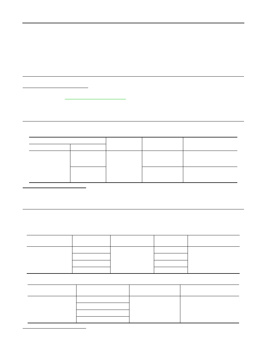
Check voltage between automatic drive positioner control unit harness connector and ground.

Is the inspection result normal?

YES

>> Tilt and telescopic sensor are OK.

NO

>> GO TO 2.

2.

CHECK TILT AND TELESCOPIC SENSOR CIRCUIT

1.

Turn ignition switch OFF.

2.

Disconnect tilt and telescopic sensor connector and automatic drive positioner control unit connector.

3.

Check continuity between tilt and telescopic sensor harness connector and automatic drive positioner
control unit harness connector.

4.

Check continuity between tilt and telescopic sensor harness connector and ground.

Is the inspection result normal?

 Tilt and telescopic sensor

Ground

Condition

Voltage (V)

(Approx.)

Connector

Terminal

M51

7

Ground

Tilt position

Change between 

1.2 (close to top)

3.4 (close to bottom)

23

Telescopic position

Change between 

0.8 (close to top)

3.4 (close to bottom)

 Tilt and telescopic sensor 

connector

Terminal

Automatic drive posi-

tioner control unit

Terminal

Continuity

M48

1

M51, M52

33

Existed

2

23

3

7

4

41

 Tilt and telescopic sensor 

connector

Terminal

Ground

Continuity

M48

1

Ground

Not existed

2

3

4

TILT&TELESCOPIC SENSOR

SE-69

< COMPONENT DIAGNOSIS >

C

D

E

F

G

H

I

K

L

M

A

B

SE

N

O

P

YES

>> GO TO 3.

NO

>> Repair or replace circuit.

3.

CHECK TILT AND TELESCOPIC SENSOR POWER SUPPLY

1.

Connect automatic drive positioner control unit connector.

2.

Check voltage between automatic drive positioner control unit harness connector and ground.

Is the inspection result normal?

YES

>> GO TO 4.

NO

>> Replace automatic drive positioner control unit. Refer to 

SE-166, "Removal and Installation"

.

4.

CHECK TILT AND TELESCOPIC SENSOR GROUND

Check continuity between automatic drive positioner control unit harness connector and ground.

Is the inspection result normal?

YES

>> Check intermittent incident. Refer to 

GI-38, "Intermittent Incident"

.

NO

>> Replace automatic drive positioner control unit. Refer to 

SE-166, "Removal and Installation"

.

Automatic drive position control unit

Ground

Voltage (V)

(Approx.)

Connector

Terminal

M52

33

5

Automatic drive position control unit

Ground

Continuity

Connector

Terminal

M52

41

Existed

SE-70

< COMPONENT DIAGNOSIS >

SLIDING MOTOR

SLIDING MOTOR

DRIVER SIDE

DRIVER SIDE : Description

INFOID:0000000001694112

With power supplied to power seat switch, sliding motor operates forward and backward slide of seat.

DRIVER SIDE : Component Function Check

INFOID:0000000001907783

1.

CHECK FUNCTION

1.

Select “SEAT SLIDE” in “Active Test” mode with CONSULT-III.

2.

Check sliding motor operation.

Is the operation of relevant parts normal?

YES

>> INSPECTION END

NO

>> Perform diagnosis procedure. Refer to 

SE-70, "DRIVER SIDE : Diagnosis Procedure"

.

DRIVER SIDE : Diagnosis Procedure

INFOID:0000000001907784

1.

CHECK SLIDING MOTOR POWER SUPPLY

1.

Turn ignition switch OFF.

2.

Disconnect sliding motor connector.

3.

Turn ignition switch ON.

4.

Perform “Active Test” (“SEAT SLIDE”) with CONSULT-lll

5.

Check voltage between sliding motor harness connector and ground.

Is the inspection result normal?

YES

>> Replace sliding motor. (Built in seat slide cushion frame.)

NO

>> GO TO 2.

2.

CHECK SLIDING MOTOR CIRCUIT

1.

Turn ignition switch OFF.

2.

Disconnect driver seat control unit connector.

3.

Check continuity between driver seat control unit harness connector and sliding motor harness connector.

Test item

Description

SEAT SLIDE

OFF

Seat sliding

Stop

FR

Forward

RR

Backward

Terminal

Test item

Voltage (V)

(Approx.)

(+)

(-)

Sliding motor

connector

Terminal

B525

35

Ground

SEAT SLIDE

OFF

0

FR (forward)

Battery voltage

RR (backward)

0

42

OFF

0

FR (forward)

0

RR (backward)

Battery voltage

Driver seat control unit

 connector

Terminal

Sliding motor

connector

Terminal

Continuity

B504

35

B525

35

Existed

42

42

SLIDING MOTOR

SE-71

< COMPONENT DIAGNOSIS >

C

D

E

F

G

H

I

K

L

M

A

B

SE

N

O

P

4.

Check continuity between driver seat control unit harness connector and ground.

Is the inspection result normal?

YES

>> GO TO 3.

NO

>> Repair or replace harness.

3.

CHECK SLIDING MOTOR

Refer to 

SE-71, "DRIVER SIDE : Component Inspection"

.

Is the inspection result normal?

YES

>> Replace driver seat control unit. Refer to 

SE-164, "Removal and Installation"

.

NO

>> Repair or replace the malfunctioning part.

DRIVER SIDE : Component Inspection

INFOID:0000000001694115

1.

CHECK SLIDING MOTOR-1

Check visually the sliding motor to see if any foreign object is not disturbing the functioning or if the sliding
motor is not broken.

Is the inspection result normal?

YES

>> GO TO 2.

NO

>> Repair or replace seat cushion frame (sliding motor).

2.

CHECK SLIDING MOTOR-2

1.

Turn ignition switch OFF.

2.

Disconnect sliding motor connector.

3.

Supply sliding motor terminals with battery voltage and check operation.

Is the inspection result normal?

YES

>> Sliding motor is OK.

NO

>> Replace sliding motor. (Built in seat cushion frame.)

PASSENGER SIDE

PASSENGER SIDE : Description

INFOID:0000000001826363

With power supplied to power seat switch, sliding motor operates forward and backward slide of seat.

PASSENGER SIDE : Component Function Check

INFOID:0000000001907880

1.

CHECK SLIDING MOTOR CIRCUIT

Check sliding operation with power seat switch.

Is the inspection results normal?

YES

>> Sliding motor is OK.

NO

>> Perform diagnosis procedure. Refer to 

SE-71, "PASSENGER SIDE : Diagnosis Procedure"

.

PASSENGER SIDE : Diagnosis Procedure

INFOID:0000000001907881

1.

CHECK SLIDING MOTOR CIRCUIT

1.

Turn ignition switch OFF.

Driver seat control unit 

connector

Terminal

Ground

Continuity 

B504

35

Not existed

42

Terminal

Operation

(+)

(–)

35

42

Forward

42

35

Backward


Content   ..  1098  1099  1100  1101   ..