Infiniti G35 (V35) Sedan. Manual - part 960
MWI
COMBINATION METER
MWI-67
< ECU DIAGNOSIS >
C
D
E
F
G
H
I
J
K
L
M
B
N
A
O
P
15
(B)
Ground
Ground
—
Ignition
switch
ON
—
0 V
16
(B)
Ground
Meter control switch ground
—
Ignition
switch
ON
—
0 V
21
(R)
Ground
Ignition signal
Input
Ignition
switch
ON
—
12 V
22
(B)
Ground
Ground
—
Ignition
switch
ON
—
0 V
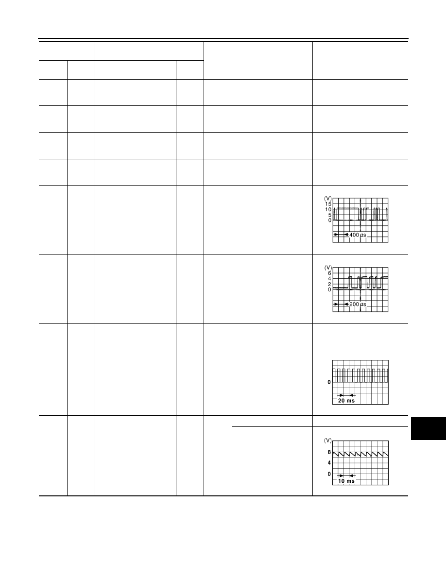
24
(BR)
Ground
Communication signal
(LCD
→
AMP.)
Output
Ignition
switch
ON
—
25
(Y)
Ground
Communication signal
(AMP.
→
LCD)
Input
Ignition
switch
ON
—
26
(R)
Ground
Vehicle speed signal
(8-pulse)
Input
Ignition
switch
ON
Speedometer operated
[When vehicle speed is ap-
prox. 40 km/h (25 MPH)]
NOTE:
The maximum voltage varies de-
pending on the specification
(destination unit).
27
(V)
Ground
Parking brake switch signal
Input
Ignition
switch
ON
Parking brake ON
0 V
Parking brake OFF
Terminal No.
(Wire color)
Description
Condition
Value
(Approx.)
+
–
Signal name
Input/
Output
JSNIA0028GB
JSNIA0027GB
JSNIA0012GB
JSNIA0007GB