Infiniti G35 (V35) Sedan. Manual - part 950


  Index      Infiniti     Infiniti G35 (V35) Sedan - service repair manual 2007 year


Search            


Content   ..  948  949  950  951   ..


Infiniti G35 (V35) Sedan. Manual - part 950


MWI

METER SYSTEM

MWI-27

< FUNCTION DIAGNOSIS >

C

D

E

F

G

H

I

J

K

L

M

B

N

A

O

P

Control outline

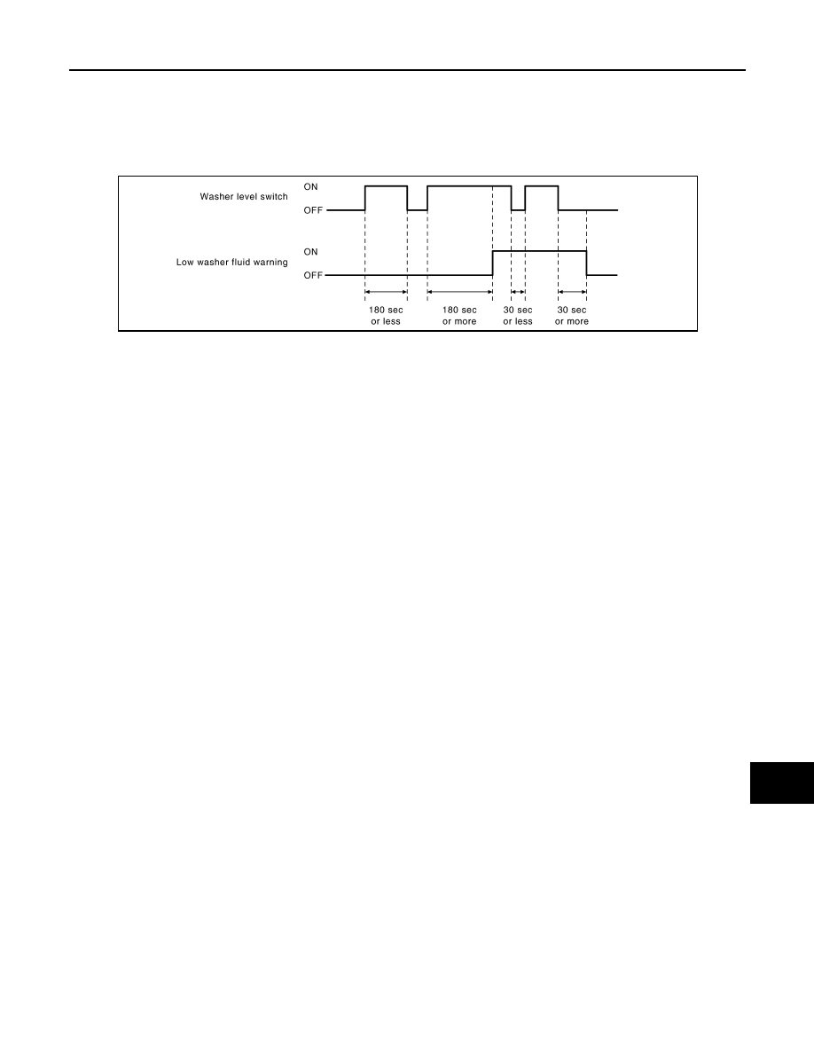
The combination meter indicates LOW WASHER FLUID WARNING judged with the signal from the washer
level switch.

Warning operation condition

• Indicates the warning when it is in washer level switch ON condition for 180 seconds or more. Release the

warning when it is in washer level switch OFF condition for 30 seconds or more.

DOOR/TRUNK OPEN WARNING

Control outline

• The combination meter indicates DOOR OPEN WARNING judged with each door switch signal received

from the unified meter and A/C amp. by means of communication line.

• The combination meter indicates TRUNK OPEN WARNING judged with the trunk switch signal received

from the unified meter and A/C amp. by means of communication line.

MPG

Control outline

• The unified meter and A/C amp. receives the fuel consumption monitor signal from ECM and the vehicle

speed signal from the ABS actuator and electric unit (control unit) with CAN communication line.

• The unified meter and A/C amp. calculates the instantaneous fuel consumption according to the fuel con-

sumption monitor signal and the vehicle speed signal received with CAN communication line, and transmits
it to the combination meter.

MPG

Control outline

• The unified meter and A/C amp. receives the fuel consumption monitor signal from ECM and the vehicle

speed signal from the ABS actuator and electric unit (control unit) with CAN communication line.

• The unified meter and A/C amp. calculates the average fuel consumption according to the fuel consumption

monitor signal and the vehicle speed signal received with CAN communication line, and transmits it to the
combination meter.

• The average fuel consumption displayed on the information display is uploaded at approximately 30-second

intervals.

NOTE:

−−−−

” is displayed for approximately 30 seconds just after the reset operation and after the ignition switch is

OFF 

 ON. It is displayed simultaneously until the vehicle drives approximately 500 m (0.31 mile).

MPH

Control outline

• The unified meter and A/C amp. receives the vehicle speed signal from the ABS actuator and electric unit

(control unit) via CAN communication line.

• Measures the time during the ignition switch ON with the unified meter and A/C amp.
• The unified meter and A/C amp. calculates the average vehicle speed according to the above signals. These

signals are transmitted to the combination meter with the communication line.

• The average vehicle speed displayed on the information display is uploaded at approximately 30-second

intervals.

NOTE:

−−−−

” is displayed for 30 seconds just after the reset operation and after the ignition switch is OFF 

 ON. It is

displayed simultaneously until the vehicle drives approximately 500 m (0.31 mile).

TIME

JSNIA0033GB

MWI-28

< FUNCTION DIAGNOSIS >

METER SYSTEM

Control outline

Measures the time during the ignition switch ON with the unified meter and A/C amp, and transmits it to the
combination meter by means of communication line.

MILES

Control outline

• The unified meter and A/C amp. transmits the vehicle speed signal from ABS actuator and electric unit (con-

trol unit) to the combination meter.

• The combination meter calculates the vehicle distance according to the vehicle speed signal. The vehicle

distance is displayed.

RANGE

Control outline

The unified meter and A/C amp. calculates possible driving distance according to the vehicle speed signal
transmitted through CAN communication and the fuel level sensor signal transmitted from the fuel level sen-
sor. These signals are transmitted to the combination meter with the communication line.
NOTE:
• “

−−−−

” is displayed for 30 seconds after the ignition switch is OFF 

 ON. It is displayed simultaneously until

the vehicle drives approximately 500 m (0.31 mile).

• The indicated values may not match each other when filling the fuel with the ignition switch ON. Refer to

MWI-154, "INFORMATION DISPLAY : Description"

.

OUTSIDE TEMP

Control outline

• - The unified meter and A/C amp. receives the ambient sensor signal from the ambient sensor.
• - The unified meter and A/C amp. calculates the ambient temperature according to the ambient sensor sig-

nal, and transmits it to the combination meter.

• - The indicated temperature is corrected by the ignition switch signal, the ambient sensor detection tempera-

ture, and the vehicle speed signal. It does not increase if the vehicle speed is less than 20 km/h (12 MPH).

Correction process (Ignition switch OFF 

 ON)

The ambient temperature sensor detection temperature is not displayed in real time if all of the following conditions are fulfilled.
The indicated temperature before the ignition switch OFF is displayed.

• The ignition switch OFF time is less than 3.5 hours
• The ambient temperature sensor detection temperature is higher than the indicated temperature before the

ignition switch OFF

Correction process (Ignition switch ON)

Perform the following correction if the ambient sensor detection temperature is higher than the indicated temperature when the
vehicle speed is 20 km/h (12 MPH) or more.

• Shorten the update time of the indicated temperature according to the increase of the vehicle speed.
• Increase the indicated temperature by 1

°

C per 1 minute until it reaches to the ambient temperature detection

value when the ambient sensor detection temperature is higher than the indicated temperature at 8

°

C or

more.

NOTE:
The ambient sensor input value that is displayed on DATA MONITOR of CONSULT-III is the value before the
correction. It may not match the indicated temperature on the information display.

SETTING

Setting item list

Items

Setting range

Setting unit

Description

ALERT

TIME TO REST

No setting - 6 hours

30 minutes, 

[60 minutes]*

TIME TO REST is displayed on the infor-
mation display if the vehicle reached the 
set travel distance.

ICY

ON/OFF

LOW OUTSIDE TEMP is displayed on the 
information display if the ambient temper-
ature is 3

°

C (37

°

F) or less.

MWI

METER SYSTEM

MWI-29

< FUNCTION DIAGNOSIS >

C

D

E

F

G

H

I

J

K

L

M

B

N

A

O

P

* : Press and hold the switch (1 second or more).

MAINTENANCE

ENGINE OIL

No setting - 18,500 miles, 
(No setting - 30,000 km)

250 miles (500 km), 

[500 miles (1000 km)]*

The engine oil replacement interval is dis-
played on the information display if the ve-
hicle reached the set distance.

OIL FILTER

No setting - 18,500 miles, 
(No setting - 30,000 km)

250 miles (500 km), 

[500 miles (1000 km)]*

The oil filter replacement interval is dis-
played on the information display if the ve-
hicle reached the set distance.

TIRE

No setting - 18,500 miles, 
(No setting - 30,000 km)

250 miles (500 km), 

[500 miles (1000 km)]*

The tire replacement interval is displayed 
on the information display if the vehicle 
reached the set distance.

OTHER

No setting - 18,500 miles, 
(No setting - 30,000 km)

250 miles (500 km), 

[500 miles (1000 km)]*

The OTHER replacement interval is dis-
played on the information display if the ve-
hicle reached the set distance.

DISPLAY

LANGUAGE

ENGLISH/FRANCAIS

Changing the language setting can be 
performed.

UNIT

US/METRIC

Changing the unit setting can be per-
formed.

Items

Setting range

Setting unit

Description

MWI-30

< FUNCTION DIAGNOSIS >

METER SYSTEM

INFORMATION DISPLAY : Component Parts Location

INFOID:0000000000964364

INFORMATION DISPLAY : Component Description

INFOID:0000000000964365

JSNIA0042ZZ

1.

Unified meter and A/C amp.

2.

BCM

3.

IPDM E/R

4.

Oil pressure switch

5.

Ambient sensor

6.

Combination meter

7.

Fuel level sensor unit (main)

8.

Fuel level sensor unit and fuel pump 
(sub)

A.

Behind cluster lid C

B.

2WD [oil pan (upper) RH side]

C.

AWD (oil filter bracket part)

D.

Condenser (front)

E.

Rear seat (lower right)

F.

Rear seat (lower left)

Unit

Description

Combination meter

Controls the information display with the signals received from the unified meter and A/C amp. by 
means of communication and the signals from various switches and sensors.

Unified meter and A/C amp.

Transmits signals received from various units to the combination meter by means of communica-
tion.

Fuel level sensor unit

Refer to 

MWI-53, "Description"

.


Content   ..  948  949  950  951   ..