Infiniti G35 (V35) Sedan. Manual - part 948


  Index      Infiniti     Infiniti G35 (V35) Sedan - service repair manual 2007 year


Search            


Content   ..  946  947  948  949   ..


Infiniti G35 (V35) Sedan. Manual - part 948


MWI

METER SYSTEM

MWI-19

< FUNCTION DIAGNOSIS >

C

D

E

F

G

H

I

J

K

L

M

B

N

A

O

P

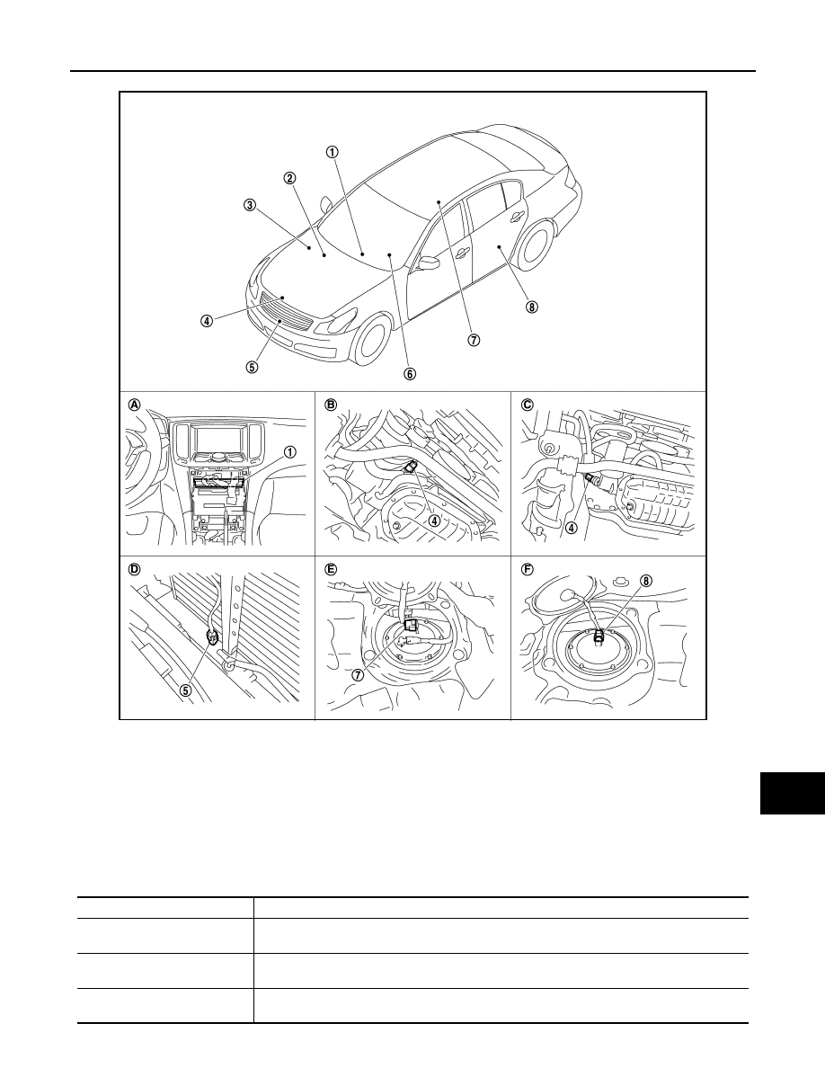
ODO/TRIP METER : Component Parts Location

INFOID:0000000000964348

ODO/TRIP METER : Component Description

INFOID:0000000000964349

JSNIA0042ZZ

1.

Unified meter and A/C amp.

2.

BCM

3.

IPDM E/R

4.

Oil pressure switch

5.

Ambient sensor

6.

Combination meter

7.

Fuel level sensor unit (main)

8.

Fuel level sensor unit and fuel pump 
(sub)

A.

Behind cluster lid C

B.

2WD [oil pan (upper) RH side]

C.

AWD (oil filter bracket part)

D.

Condenser (front)

E.

Rear seat (lower right)

F.

Rear seat (lower left)

Unit

Description

Combination meter

The combination meter calculates the vehicle distance according to the vehicle speed signal. The 
vehicle distance is displayed.

Unified meter and A/C amp.

The unified meter and A/C amp. transmits the vehicle speed signal from ABS actuator and electric 
unit (control unit) to the combination meter.

ABS actuator and electric unit 
(control unit)

Transmits the vehicle speed signal to the unified meter and A/C amp. with CAN communication 
line.

MWI-20

< FUNCTION DIAGNOSIS >

METER SYSTEM

SHIFT POSITION INDICATOR

SHIFT POSITION INDICATOR : System Diagram

INFOID:0000000000964350

SHIFT POSITION INDICATOR : System Description

INFOID:0000000000964351

Shift position is displayed in the information display LCD in the combination meter.

MANUAL MODE

When operated with A/T device

• Unified meter and A/C amp. inputs manual mode signal and shift-up/down signal from A/T device (manual

mode switch), and transmits the signals to TCM with CAN communication line.

• TCM processes manual mode signal and shift-up/down signal, and transmits manual mode indicator signal

and shift position signal to unified meter and A/C amp. with CAN communication line.

• Unified meter and A/C amp. transmits manual mode indicator signal and shift position signal to combination

meter with the communication line.

• Combination meter indicates A/T gear position and manual mode indicator, when receiving manual mode

indicator signal and sift position signal.

When operated with paddle shifter

• The unified meter and A/C amp. receives the manual mode signal from the A/T device (manual mode

switch) or the shifter-up/down signal from the paddle shifter and transmits them to TCM via CAN communi-
cation line.

• TCM processes manual mode signal and paddle shifter-up/down signal, and transmits manual mode indica-

tor signal and shift position signal to unified meter and A/C amp. with CAN communication line.

• Unified meter and A/C amp. transmits manual mode indicator signal and shift position signal to combination

meter with the communication line.

• Combination meter indicates A/T gear position and manual mode indicator, when receiving manual mode

indicator signal and shift position signal.

NOT MANUAL MODE

• Unified meter and A/C amp. inputs not manual mode signal from A/T device (manual mode switch), and

transmits the signals to TCM with CAN communication line.

• TCM transmits shift position signal to unified meter and A/C amp. with CAN communication line.
• Unified meter and A/C amp. transmits shift position signal to combination meter with the communication line.
• Combination meter indicates A/T shift position when receiving shift position signal.

JSNIA0029GB

MWI

METER SYSTEM

MWI-21

< FUNCTION DIAGNOSIS >

C

D

E

F

G

H

I

J

K

L

M

B

N

A

O

P

SHIFT POSITION INDICATOR : Component Parts Location

INFOID:0000000000964352

SHIFT POSITION INDICATOR : Component Description

INFOID:0000000000964353

JSNIA0042ZZ

1.

Unified meter and A/C amp.

2.

BCM

3.

IPDM E/R

4.

Oil pressure switch

5.

Ambient sensor

6.

Combination meter

7.

Fuel level sensor unit (main)

8.

Fuel level sensor unit and fuel pump 
(sub)

A.

Behind cluster lid C

B.

2WD [oil pan (upper) RH side]

C.

AWD (oil filter bracket part)

D.

Condenser (front)

E.

Rear seat (lower right)

F.

Rear seat (lower left)

Unit

Description

Combination meter

Displays the shift position on the information display with shift position signal and manual mode in-
dicator signal received from unified meter and A/C amp.

Unified meter and A/C amp.

• Transmits the signals from the A/T device and paddle shifter switch to TCM with CAN communi-

cation line.

• Transmits shift position signal and manual mode indicator signal received from TMC with CAN 

communication line to the combination meter by means of communication line.

MWI-22

< FUNCTION DIAGNOSIS >

METER SYSTEM

WARNING LAMPS/INDICATOR LAMPS

WARNING LAMPS/INDICATOR LAMPS : System Diagram

INFOID:0000000000964354

WARNING LAMPS/INDICATOR LAMPS : System Description

INFOID:0000000000964355

OIL PRESSURE WARNING LAMP

• IPDM E/R inputs oil pressure switch signal from oil pressure switch, and transmits the signal to unified meter

and A/C amp. through BCM with CAN communication line.

• Unified meter and A/C amp. transmits oil pressure switch signal to combination meter with communication

line.

• Let the combination meter turn oil pressure warning lamp ON with received oil pressure switch signal.

A/T device

Transmits the following signals to the unified meter and A/C amp.

• Manual mode signal

• Not manual mode signal

• Manual mode shift up signal

• Manual mode shift down signal

Paddle shifter

Transmits the paddle shifter up signal and paddle shifter down signal to the unified meter and A/C 
amp.

TCM

Transmits shift position signal and manual mode indicator signal to the unified meter and A/C amp.

Unit

Description

JSNIA0163GB


Content   ..  946  947  948  949   ..