Infiniti G35 (V35) Sedan. Manual - part 922


  Index      Infiniti     Infiniti G35 (V35) Sedan - service repair manual 2007 year


Search            


Content   ..  920  921  922  923   ..


Infiniti G35 (V35) Sedan. Manual - part 922


CHANGE OVER SWITCH

MIR-15

< COMPONENT DIAGNOSIS >

[WITH ADP]

C

D

E

F

G

H

I

J

K

M

A

B

MIR

N

O

P

NO

>> Repair or replace harness.

3.

CHECK DOOR MIRROR REMOTE CONTROL SWITCH GROUND CIRCUIT

Check continuity between door mirror remote control switch connector and ground.

Is the inspection result normal?

YES

>> GO TO 4.

NO

>> Repair or replace harness.

4.

CHECK AUTOMATIC DRIVE POSITIONER CONTROL UNIT OUTPUT SIGNAL

1.

Connect automatic drive positioner control unit connector.

2.

Turn ignition switch ON.

3.

Check voltage between automatic drive positioner control unit connector and ground.

Is the inspection result normal?

YES

>> GO TO 5.

NO

>> Replace automatic drive positioner control unit. Refer to 

ADP-218, "Removal and Installation"

.

5.

CHECK CHANGEOVER SWITCH

Check changeover switch.
Refer to 

MIR-15, "Component Inspection"

.

Is the inspection result normal?

YES

>> Refer to 

GI-39, "Intermittent Incident"

.

NO

>> Replace door mirror remote control switch. Refer to 

MIR-68, "Removal and Installation"

.

6.

CHECK INTERMITTENT INCIDENT

Check intermittent incident.
Refer to 

GI-39, "Intermittent Incident"

.

Is the inspection result normal?

YES

>> Replace automatic drive positioner control unit. Refer to 

ADP-218, "Removal and Installation"

.

NO

>> Repair or replace the malfunctioning parts.

Component Inspection

INFOID:0000000000962323

1.

CHECK CHANGEOVER SWITCH 

Check door mirror remote control switch.

Is the inspection result normal?

YES

>> INSPECTION END.

NO

>> Replace door mirror remote control switch. Refer to 

MIR-68, "Removal and Installation"

.

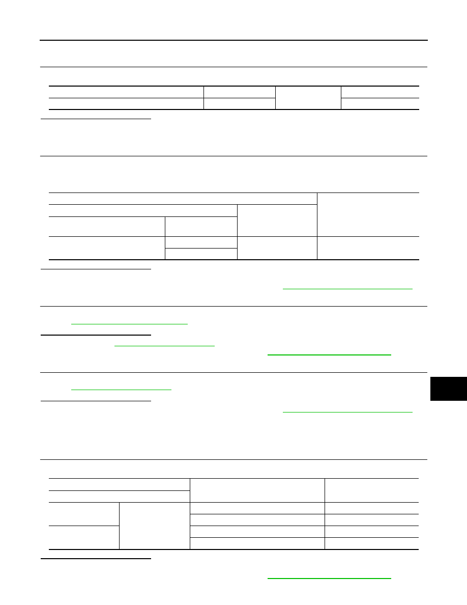
Door mirror remote control switch connector

Terminal

Ground

Continuity

D7

7

Existed

Terminals

Voltage (V)

(Approx.)

(+)

(-)

Automatic drive positioner control unit 

connector

Terminal

M51

2

Ground

5

18

Terminal

Change over switch condition

Continuity

Door mirror remote control switch

10

7

LEFT

Existed

Other than above

Not existed

11

RIGHT

Existed

Other than above

Not existed

MIR-16

< COMPONENT DIAGNOSIS >

[WITH ADP]

DOOR MIRROR MOTOR

DOOR MIRROR MOTOR

Description

INFOID:0000000000962324

It makes mirror face operate from side to side and up and down with the electric power that AUTOMATIC
DRIVE POSITIONER CONTROL UNIT supplies.

Component Function Check

INFOID:0000000000962325

1.

CHECK DOOR MIRROR MOTOR FUNCTION

Check the operation with “MIRROR MOTOR RH” and “MIRROR MOTOR LH” in  “ACTIVE TEST” mode with
CONSULT-III
Refer to 

ADP-48, "CONSULT-III Function"

.

Is the inspection result normal?

YES

>> Door mirror motor function is OK.

NO

>> Refer to 

MIR-16, "Diagnosis Procedure"

.

Diagnosis Procedure

INFOID:0000000000962326

1.

CHECK DOOR MIRROR MOTOR INPUT SIGNAL

1.

Turn ignition switch ON.

2.

Check voltage between door mirror connector and ground.

Is the inspection result normal?

YES

>> Refer to 

MIR-18, "Component Inspection"

.

NO

>> GO TO 2.

2.

CHECK HARNESS CONTINUITY

1.

Turn ignition switch OFF.

2.

Disconnect automatic drive positioner control unit connector and door mirror connector.

3.

Check continuity between automatic drive positioner control unit connector and door mirror connector.

  [Door mirror driver side]

[Door mirror passenger side]

Terminals

Door mirror remote control switch 

condition

Voltage (V)

(Approx.)

(+)

(–)

Door mirror 

connector

Terminal

D3 (Driver side)

D33 (Passenger side)

5

Ground

UP

Battery voltage

Other than above

0

6

LEFT

Battery voltage

Other than above

0

7

DOWN / RIGHT

Battery voltage

Other than above

0

Automatic drive positioner con-

trol unit connector

Terminal

Door mirror (driver side) connec-

tor

Terminal

Continuity

M51

16

D3

7

Existed

31

5

32

6

Automatic drive positioner control 

unit connector

Terminal

Door mirror (passenger side) 

connector

Terminal

Continuity

M51

14

D33

5

Existed

15

6

30

7

DOOR MIRROR MOTOR

MIR-17

< COMPONENT DIAGNOSIS >

[WITH ADP]

C

D

E

F

G

H

I

J

K

M

A

B

MIR

N

O

P

4.

Check continuity between automatic drive positioner control unit connector and ground.

[Door mirror driver side]

[Door mirror passenger side]

Is the inspection result normal?

YES

>> GO TO 3.

NO

>> Repair or replace harness.

3.

CHECK AUTOMATIC DRIVE POSITIONER CONTROL UNIT OUTPUT SIGNAL

1.

Connect automatic drive positioner control unit connector.

2.

Turn ignition switch ON.

3.

Check voltage between automatic drive positioner control unit connector and ground.

[Door mirror driver side]

[Door mirror passenger side]

Is the inspection result normal?

YES

>> Refer to 

MIR-18, "Component Inspection"

.

NO

>> Replace automatic drive positioner control unit. Refer to 

ADP-218, "Removal and Installation"

.

4.

CHECK DOOR MIRROR MOTOR

Check door mirror motor.
Refer to 

MIR-18, "Component Inspection"

.

Automatic drive positioner control unit connec-

tor

Terminal

Ground

Continuity

M51

16

Not existed

31

32

Automatic drive positioner control unit connec-

tor

Terminal

Ground

Continuity

M51

14

Not existed

15

30

Terminals

Mirror switch condition

Voltage (V)

(Approx.)

(+)

(-)

Automatic drive positioner con-

trol unit connector

Terminal

M51

16

Ground

DOWN / RIGHT

Battery voltage

Other than above

0

31

UP

Battery voltage

Other than above

0

32

LEFT

Battery voltage

Other than above

0

Terminals

Mirror switch condition

Voltage (V)

(Approx.)

(+)

(-)

Automatic drive positioner con-

trol unit connector

Terminal

M51

14

Ground

UP

Battery voltage

Other than above

0

15

LEFT

Battery voltage

Other than above

0

30

DOWN / RIGHT

Battery voltage

Other than above

0

MIR-18

< COMPONENT DIAGNOSIS >

[WITH ADP]

DOOR MIRROR MOTOR

Is the inspection result normal?

YES

>> Refer to 

GI-39, "Intermittent Incident"

.

NO

>> Replace door mirror. Refer to 

MIR-67, "Removal and Installation"

.

Component Inspection

INFOID:0000000000962327

1.

CHECK DOOR MIRROR MOTOR-I

Check that door mirror motor does not trap foreign objects and does not have any damage.
Refer to 

MIR-69, "Exploded View"

.

Is the inspection result normal?

YES

>> GO TO 2.

NO

>> Replace door mirror.Refer to 

MIR-67, "Removal and Installation"

.

2.

CHECK DOOR MIRROR MOTOR-II

1.

Turn ignition switch OFF.

2.

Disconnect door mirror connector.

3.

Apply 12V to each power supply terminal of door mirror motor.

Is the inspection result normal?

YES

>> INSPECTION END.

NO

>> Replace door mirror. Refer to 

MIR-67, "Removal and Installation"

.

Door mirror connector

Terminal

Operational direction

(+)

(–)

D3 (Driver side)

D33 (Passenger side)

7

6

RIGHT

6

7

LEFT

5

7

UP

7

5

DOWN


Content   ..  920  921  922  923   ..