Infiniti G35 (V35) Sedan. Manual - part 317
CO-16
< ON-VEHICLE REPAIR >
RADIATOR
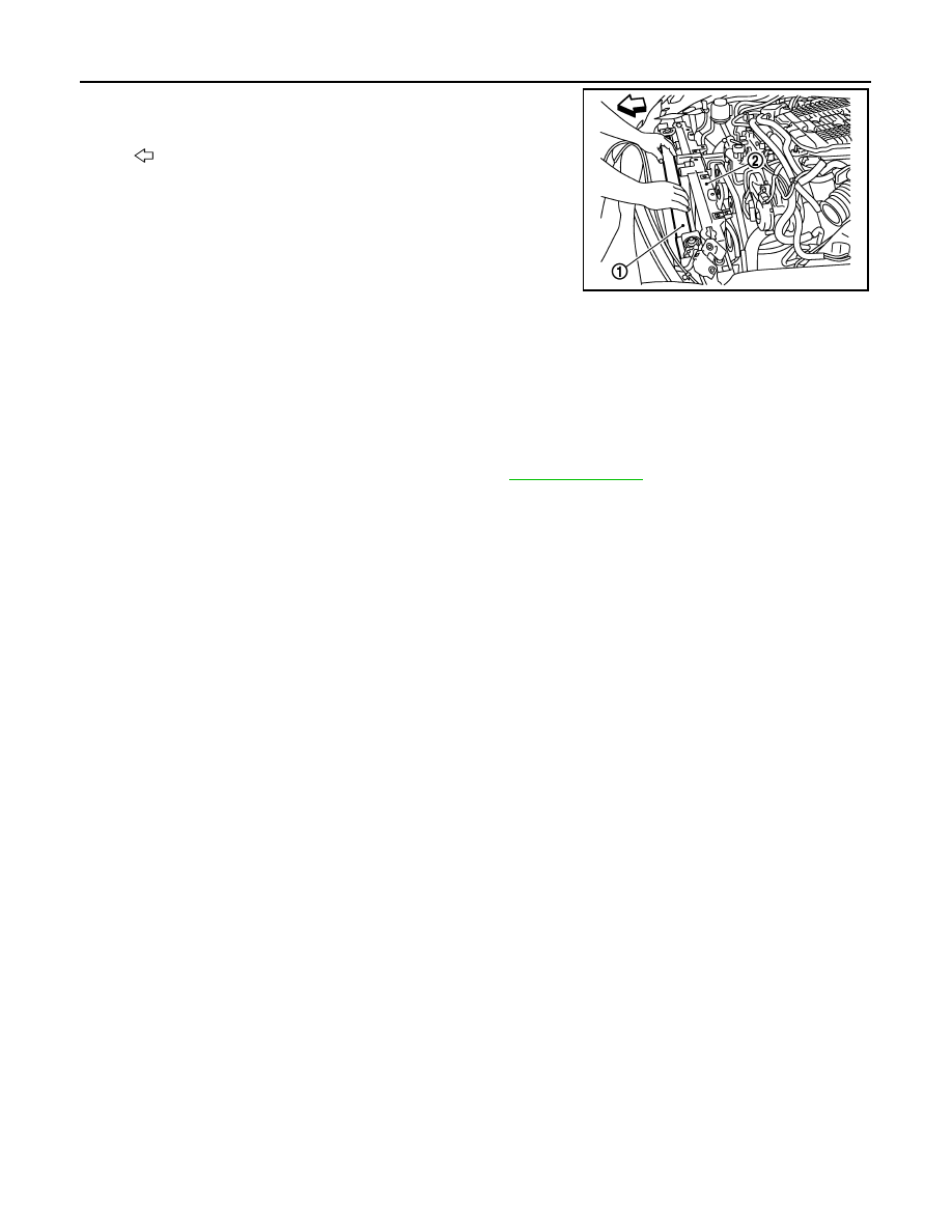
b.
Remove radiator & condenser assembly (1) from front of radia-
tor core support (2).
INSTALLATION
Installation is the reverse order of removal.
Inspection
INFOID:0000000000956346
INSPECTION AFTER INSTALLATION
• Check that the reservoir tank cap is tightened.
• Check for leaks of engine coolant using the radiator cap tester adapter [SST: EG17650301 (J33984-A)] and
the radiator cap tester (commercial service tool). Refer to
.
• Start and warm up the engine. Visually make sure that there is no leaks of engine coolant and A/T fluid (A/T
models).
: Vehicle front
JPBIA0107ZZ