Infiniti G35 (V35) Sedan. Manual - part 316
CO-12
< ON-VEHICLE MAINTENANCE >
RADIATOR
RADIATOR
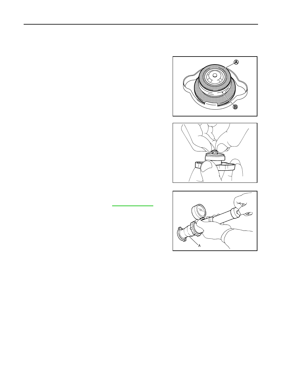
RADIATOR CAP
RADIATOR CAP : Inspection
INFOID:0000000000956342
• Check valve seat of radiator cap.
- Check if valve seat is swollen to the extent that the edge of the
plunger cannot be seen when watching it vertically from the top.
- Check if valve seat has no soil and damage.
• Pull negative-pressure valve to open it, and make sure that it close
completely when released.
- Make sure that there is no dirt or damage on the valve seat of radi-
ator cap negative-pressure valve.
- Make sure that there are no unusualness in the opening and clos-
ing conditions of negative-pressure valve.
• Check radiator cap relief pressure.
- When connecting radiator cap to the radiator cap tester and the
radiator cap tester adapter (commercial service tool) (A), apply
engine coolant to the cap seal surface.
• Replace radiator cap if there is an unusualness related to the above three.
CAUTION:
When installing radiator cap, thoroughly wipe out the water outlet (front) filler neck to remove any
waxy residue or foreign material.
RADIATOR
RADIATOR : Inspection
INFOID:0000000000956343
Check radiator for mud or clogging. If necessary, clean radiator as follows:
• Be careful not to bend or damage radiator fins.
• When radiator is cleaned without removal, remove all surrounding parts such as radiator cooling fan assem-
bly and horns. Then tape harness and connectors to prevent water from entering.
1.
Apply water by hose to the back side of the radiator core vertically downward.
2.
Apply water again to all radiator core surfaces once per minute.
3.
Stop washing if any stains no longer flow out from radiator.
4.
Blow air into the back side of radiator core vertically downward.
A
: Valve seat
B
: Metal plunger
JPBIA0108ZZ
SMA967B
Standard and limit
: Refer to
JPBIA0109ZZ