Infiniti G35 (V35) Sedan. Manual - part 238
BRC-26
< FUNCTION DIAGNOSIS >
[VDC/TCS/ABS]
DIAGNOSIS SYSTEM [ABS ACTUATOR AND ELECTRIC UNIT (CONTROL
UNIT)]
DIAGNOSIS SYSTEM [ABS ACTUATOR AND ELECTRIC UNIT (CONTROL
UNIT)]
CONSULT-III Function (ABS)
INFOID:0000000000958517
FUNCTION
CONSULT-III can display each diagnostic item using the diagnostic test modes shown following.
SELF-DIAG RESULTS MODE
Operation Procedure
1.
Before performing the self-diagnosis, start engine and drive vehicle at 30 km/h (19 MPH) or more for
approximately 1 minute.
How to Erase Self-diagnosis Results
1.
After erasing DTC memory, start engine and drive vehicle at 30 km/h (19 MPH) or more for approximately
1 minute as the final inspection, and make sure that the ABS warning lamp, VDC OFF indicator lamp,
SLIP indicator lamp and brake warning lamp turn OFF.
CAUTION:
If memory cannot be erased, perform applicably diagnosis.
NOTE:
• When the wheel sensor malfunctions, after inspecting the wheel sensor system, the ABS warning lamp,
VDC OFF indicator lamp, SLIP indicator lamp and brake warning lamp will not turn OFF even when the
system is normal unless the vehicle is driving at approximately 30 km/h (19 MPH) or more for approxi-
mately 1 minute.
• Brake warning lamp will turn ON in case of parking brake operation (when switch is ON) or of brake fluid
level switch operation (when brake fluid is insufficient).
• VDC OFF switch should not stay “ON” position.
Display Item List
DATA MONITOR MODE
Display Item List
×
: Applicable
❏
: Optional item
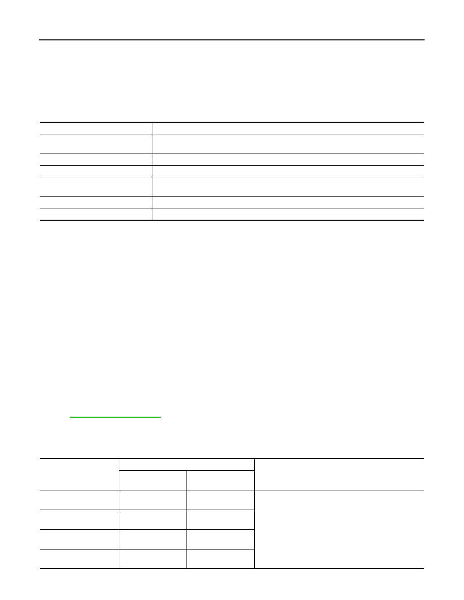
Diagnostic test mode
Function
Work support
This mode enables a technician to adjust some devices faster and more accurately by following
the indications on CONSULT-III.
Self-diagnostic results
Self-diagnostic results can be read and erased quickly.
Data monitor
Input/Output data in the ABS actuator and electric unit (control unit) can be read.
Active test
Diagnostic test mode is which CONSULT-III drives some actuators apart from the ABS actuator
and electric unit (control unit) and also shifts some parameters in a specified range.
ECU part number
ABS actuator and electric unit (control unit) part number can be read.
CAN diagnostic support monitor
The results of transmit/receive diagnosis of CAN communication can be read.
Monitor item (Unit)
SELECT MONITOR ITEM
Remarks
ECU INPUT SIG-
NALS
MAIN SIGNLAS
FR LH SENSOR
[km/h (MPH)]
×
×
Wheel speed
FR RH SENSOR
[km/h (MPH)]
×
×
RR LH SENSOR
[km/h (MPH)]
×
×
RR RH SENSOR
[km/h (MPH)]
×
×