Index Infiniti Infiniti G35 (V35) Sedan - service repair manual 2007 year
Search
Content .. 81 82 83 84 ..
Infiniti G35 (V35) Sedan. Manual - part 83
AV-104
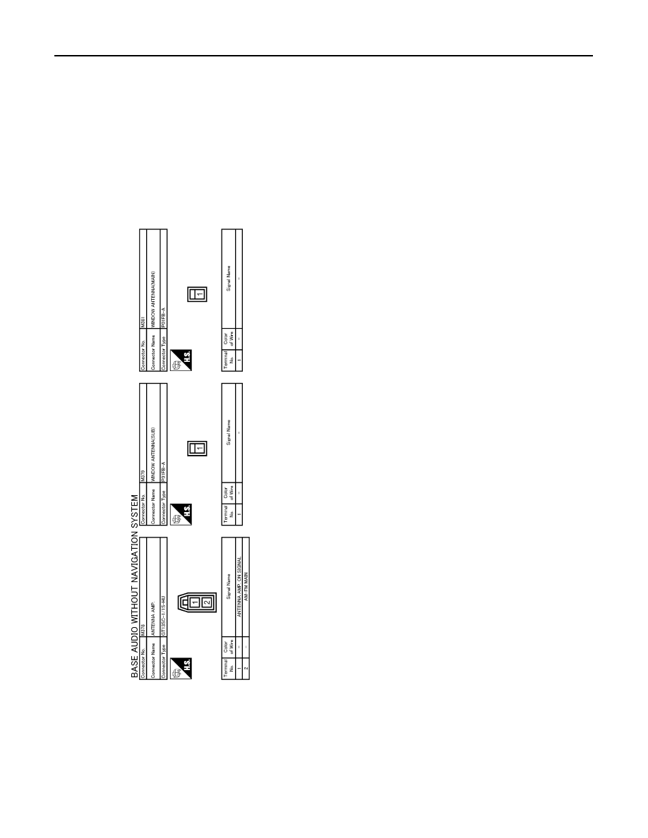
< ECU DIAGNOSIS >
[BASE AUDIO WITHOUT NAVIGATION]
SATELLITE RADIO TUNER
JCNWA0031GB