Infiniti G20 (P11). Manual - part 442
Temperature °C (°F)
Resistance k
Ω
35 (95)
1.51
40 (104)
1.27
45 (113)
1.07
If NG, replace in-vehicle sensor.
RHA077H
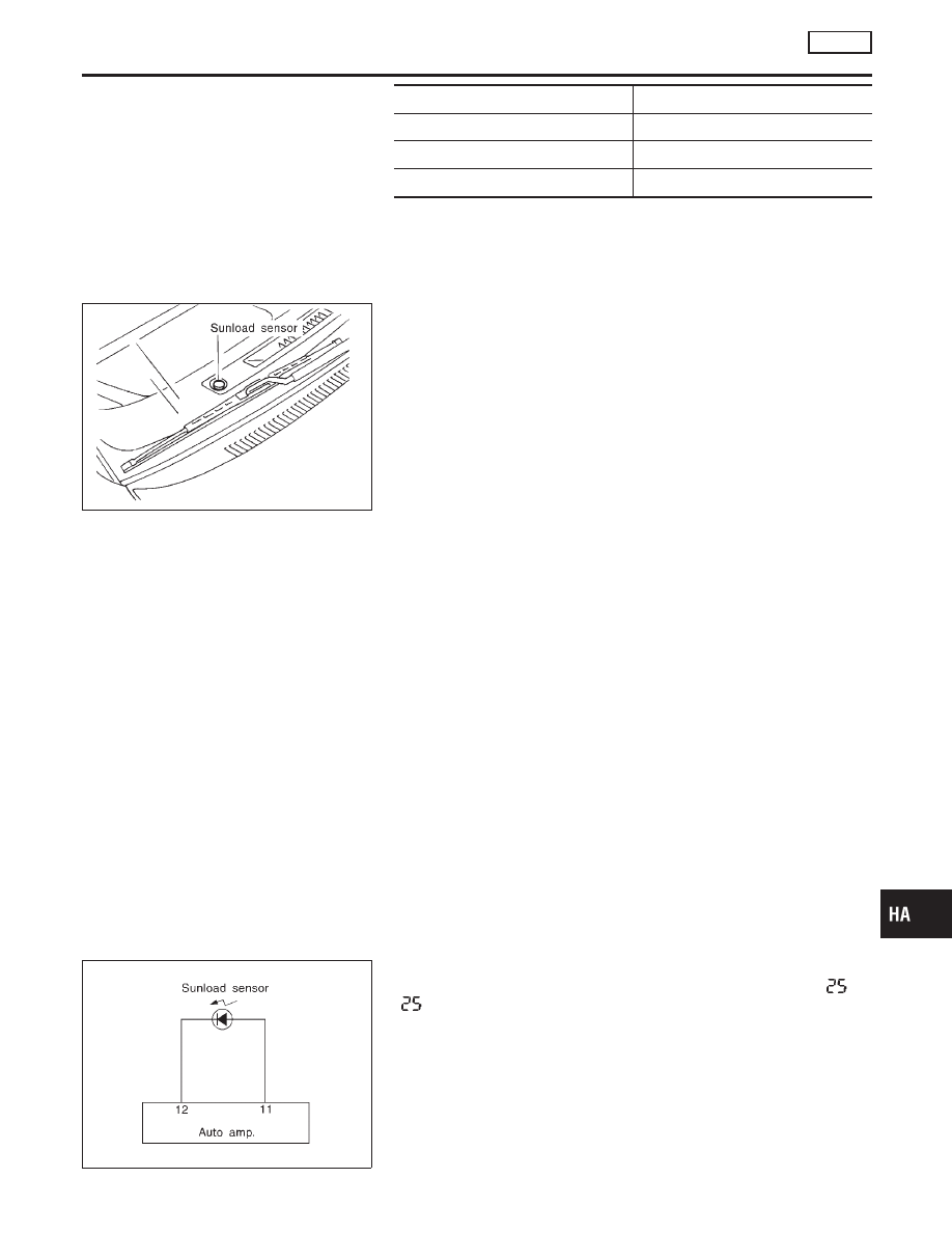
Sunload Sensor Circuit
COMPONENT DESCRIPTION
NCHA0046
The sunload sensor is located on the right defroster grille. It detects
sunload entering through windshield by means of a photo diode.
The sensor converts the sunload into a current value which is then
input into the auto amplifier.
SUNLOAD INPUT PROCESS
NCHA0047
The auto amp. also includes a processing circuit which “average”
the variations in detected sunload over a period of time. This pre-
vents drastic swings in the ATC system operation due to small or
quick variations in detected sunload.
For example, consider driving along a road bordered by an occa-
sional group of large trees. The sunload detected by the sunload
sensor will vary whenever the trees obstruct the sunlight. The pro-
cessing circuit averages the detected sunload over a period of
time, so that the (insignificant) effect of the trees momentarily
obstructing the sunlight does not cause any change in the ATC
system operation. On the other hand, shortly after entering a long
tunnel, the system will recognize the change in sunload, and the
system will react accordingly.
RHA061GA
DIAGNOSTIC PROCEDURE
NCHA0048
SYMPTOM: Sunload sensor circuit is open or shorted. (
or
−
is indicated on auto amp. as a result of conducting Self-
diagnosis STEP 2.)
GI
MA
EM
LC
EC
FE
CL
MT
AT
AX
SU
BR
ST
RS
BT
SC
EL
IDX
TROUBLE DIAGNOSES
AUTO
In-vehicle Sensor Circuit (Cont’d)
HA-99