Infiniti G20 (P11). Manual - part 441
RHA073HB
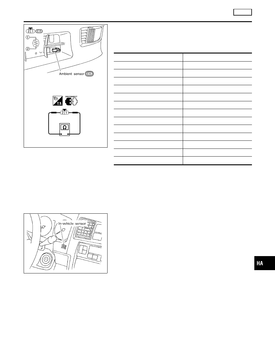
ELECTRICAL COMPONENT INSPECTION
NCHA0042
Ambient Sensor
NCHA0042S01
After disconnecting ambient sensor harness connector, measure
resistance between terminals 2 and 1 at sensor harness side, using
the table below.
Temperature °C (°F)
Resistance k
Ω
−15 (5)
12.73
−10 (14)
9.92
−5 (23)
7.80
0 (32)
6.19
5 (41)
4.95
10 (50)
3.99
15 (59)
3.24
20 (68)
2.65
25 (77)
2.19
30 (86)
1.81
35 (95)
1.51
40 (104)
1.27
45 (113)
1.07
If NG, replace ambient sensor.
RHA074H
In-vehicle Sensor Circuit
COMPONENT DESCRIPTION
NCHA0043
In-vehicle sensor
NCHA0043S01
The in-vehicle sensor is located on instrument lower panel. It con-
verts variations in temperature of compartment air drawn from the
aspirator into a resistance value. It is then input into the auto
amplifier.
GI
MA
EM
LC
EC
FE
CL
MT
AT
AX
SU
BR
ST
RS
BT
SC
EL
IDX
TROUBLE DIAGNOSES
AUTO
Ambient Sensor Circuit (Cont’d)
HA-95