Infiniti G20 (P11). Manual - part 386
SEM715A
SEM998C
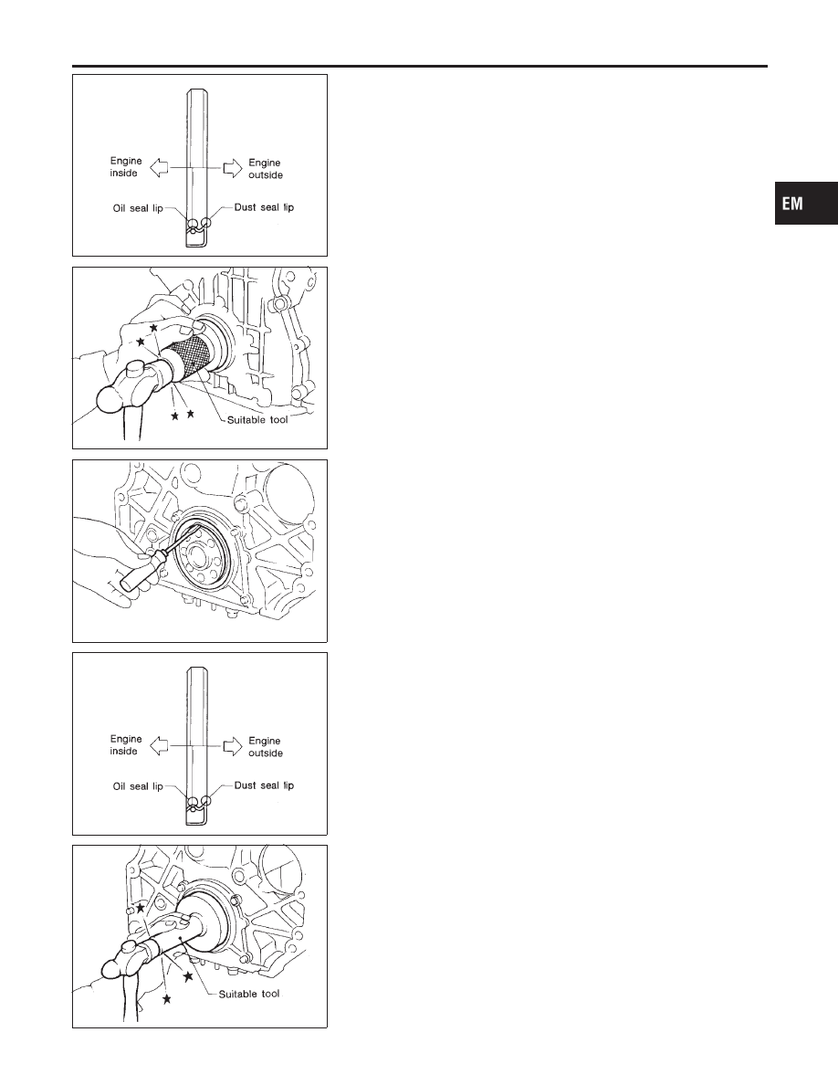
3.
Apply new engine oil to new oil seal and install it using a suit-
able tool.
I
Install new oil seal in the direction shown.
SEM999C
REAR OIL SEAL
NCEM0015S03
1.
Remove transaxle. (Refer to MT or AT section.)
2.
Remove flywheel or drive plate.
3.
Remove rear oil seal.
I
Be careful not to scratch rear oil seal retainer.
SEM715A
SEM001D
4.
Apply new engine oil to new oil seal and install it using a suit-
able tool.
I
Install new oil seal in the direction shown.
GI
MA
LC
EC
FE
CL
MT
AT
AX
SU
BR
ST
RS
BT
HA
SC
EL
IDX
OIL SEAL
Replacement (Cont’d)
EM-29