Infiniti G20 (P11). Manual - part 387


  Index      Infiniti     Infiniti G20 (P11) - service repair manual 1999-2002 year


Search            


Content   ..  385  386  387  388   ..


Infiniti G20 (P11). Manual - part 387


SEM590G

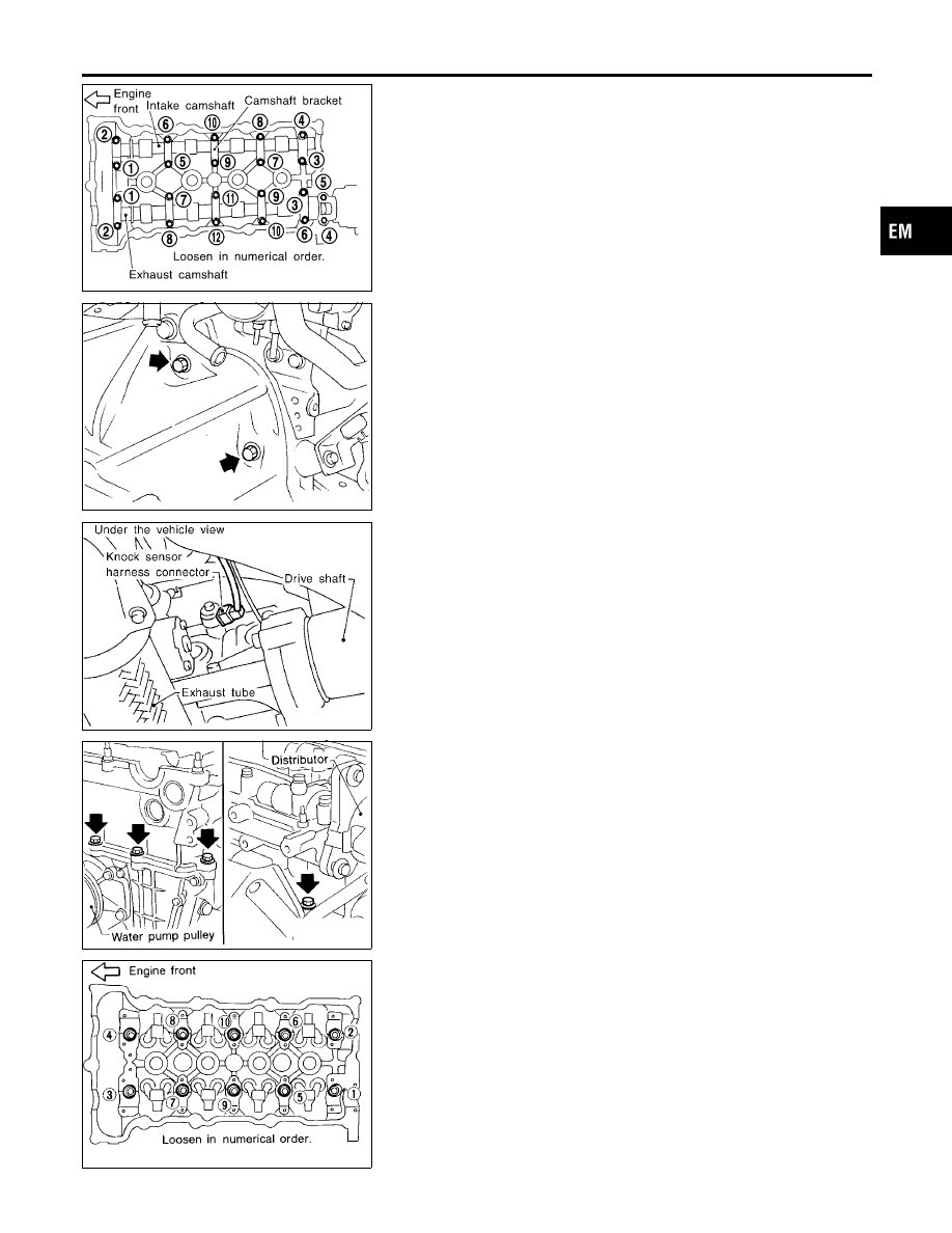
20. Remove camshafts and camshaft brackets.

SEM354D

21. Remove starter motor.

MEC756B

22. Remove the following water hoses:

I

Water hose to water pump.

I

Water hoses for heater.

23. Remove knock sensor harness connector.

SEM977C

24. Remove cylinder head outside bolts.

SEM978C

25. Remove cylinder head bolts.

I

Bolts should be loosened in two or three steps.

26. Remove cylinder head completely with intake and exhaust

manifolds.

GI

MA

LC

EC

FE

CL

MT

AT

AX

SU

BR

ST

RS

BT

HA

SC

EL

IDX

CYLINDER HEAD

Removal (Cont’d)

EM-33

Disassembly

NCEM0018

CAUTION:

I

When installing rocker arms, camshaft and oil seal, lubri-
cate contacting surfaces with new engine oil.

I

When tightening cylinder head bolts, camshaft sprocket
bolts and camshaft bracket bolts, lubricate bolt threads
and seat surfaces with new engine oil.

AEM116

I

If a hydraulic lash adjuster is kept on its side, there is a
risk of air entering it. When hydraulic lash adjusters are
removed, stand them straight up or soak them in new
engine oil.

I

Do not disassemble hydraulic lash adjusters.

I

Attach tags to lash adjusters so as not to mix them up.

SEM057G

1.

Remove rocker arms, shims, rocker arm guides and hydraulic
lash adjusters from cylinder head.

CAUTION:

Keep parts in order so they can be installed in their original
positions during assembly.

SEM058G

2.

Remove exhaust manifold cover.

3.

Remove EGR tube.

SEM059G

4.

Remove exhaust manifold as shown.

CYLINDER HEAD

Disassembly

EM-34

SEM060G

5.

Remove EGR volume control valve assembly.

SEM082D

6.

Remove water outlet.

SEM061G

7.

Remove intake manifold with intake manifold collector as
shown.

SEM053G

8.

Remove valve components with Tool. Install camshaft tempo-
rarily.

SEM054G

9.

Remove valve oil seal with a suitable tool.

GI

MA

LC

EC

FE

CL

MT

AT

AX

SU

BR

ST

RS

BT

HA

SC

EL

IDX

CYLINDER HEAD

Disassembly (Cont’d)

EM-35

SEM925C

Inspection

NCEM0019

CYLINDER HEAD DISTORTION

NCEM0019S01

I

Clean mating surface of cylinder head.

I

Use a reliable straightedge and feeler gauge to check the flat-
ness of cylinder head mating surface.

I

Check along six positions shown in figure.

Head surface flatness:

Standard: Less than 0.03 mm (0.0012 in)
Limit: 0.1 mm (0.004 in)

If beyond the specified limit, replace or resurface it.
Resurfacing limit:
The limit for cylinder head resurfacing is determined by the
amount of cylinder block resurfacing.
Amount of cylinder head resurfacing is “A”.
Amount of cylinder block resurfacing is “B”.

The maximum limit is as follows:

A + B = 0.2 mm (0.008 in)

After resurfacing cylinder head, check that camshaft rotates freely
by hand. If resistance is felt, cylinder head must be replaced.

Nominal cylinder head height:

136.9 - 137.1 mm (5.390 - 5.398 in)

SEM926C

CAMSHAFT VISUAL CHECK

NCEM0019S02

Check camshaft for scratches, seizure and wear.

CAMSHAFT RUNOUT

NCEM0019S03

1.

Measure camshaft runout at the center journal.

Runout (Total indicator reading):

Standard

Less than 0.02 mm (0.0008 in)

Limit

0.1 mm (0.004 in)

2.

If it exceeds the limit, replace camshaft.

SEM549A

CAMSHAFT CAM HEIGHT

NCEM0019S04

1.

Measure camshaft cam height.

Standard cam height:

Intake

37.550 - 37.740 mm (1.4783 - 1.4858 in)

Exhaust

37.920 - 38.110 mm (1.4929 - 1.5004 in)

Cam height wear limit:

Intake & Exhaust

0.2 mm (0.008 in)

2.

If wear is beyond the limit, replace camshaft.

CYLINDER HEAD

Inspection

EM-36


Content   ..  385  386  387  388   ..