Infiniti G20 (P11). Manual - part 329


  Index      Infiniti     Infiniti G20 (P11) - service repair manual 1999-2002 year


Search            


Content   ..  327  328  329  330   ..


Infiniti G20 (P11). Manual - part 329


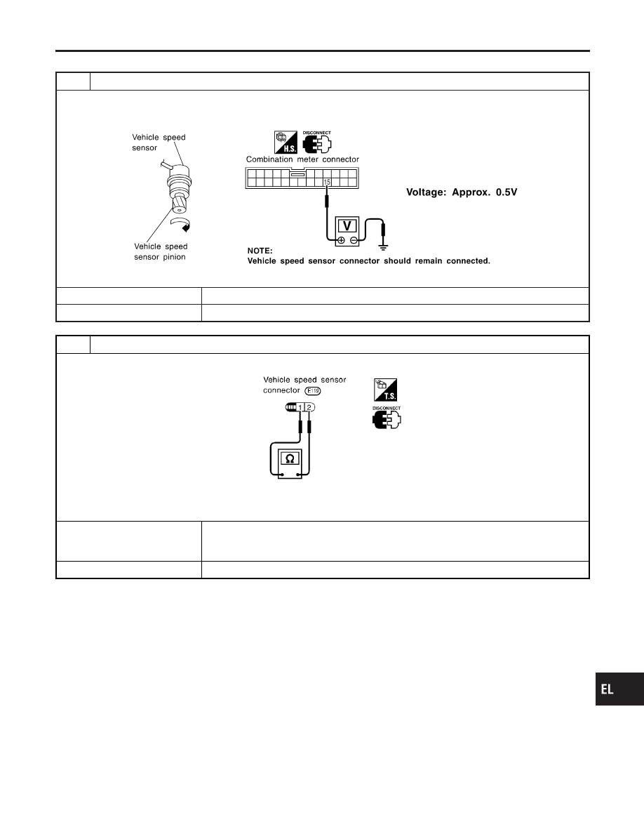
INSPECTION/VEHICLE SPEED SENSOR

=NCEL0198S04

1

CHECK VEHICLE SPEED SENSOR OUTPUT

1. Remove vehicle speed sensor from transmission.
2. Check voltage between combination meter harness connector M41 terminal 15 (R) and ground while quickly turning

speed sensor pinion.

SEL273Y

OK or NG

OK

©

Vehicle speed sensor is OK.

NG

©

GO TO 2.

2

CHECK VEHICLE SPEED SENSOR

Check resistance between vehicle speed sensor terminals 1 and 2.

SEL776V

Resistance: Approx. 250

OK or NG

OK

©

Check the following.

I

Harness or connector between speedometer and vehicle speed sensor

I

Harness between vehicle speed sensor and ground

NG

©

Replace vehicle speed sensor.

GI

MA

EM

LC

EC

FE

CL

MT

AT

AX

SU

BR

ST

RS

BT

HA

SC

IDX

METERS AND GAUGES

Trouble Diagnoses (Cont’d)

EL-93

INSPECTION/ENGINE REVOLUTION SIGNAL

=NCEL0198S05

1

CHECK ECM OUTPUT

1. Start engine.
2. Check voltage between combination meter harness connector M41 terminals 16 (L) and ground at idle and 2,000 rpm.

SEL364WC

OK or NG

OK

©

Engine revolution signal is OK.

NG

©

Harness for open or short between ECM and combination meter

METERS AND GAUGES

Trouble Diagnoses (Cont’d)

EL-94

INSPECTION/FUEL LEVEL SENSOR UNIT

=NCEL0198S06

1

CHECK GROUND CIRCUIT FOR FUEL LEVEL SENSOR UNIT

Check harness continuity between fuel level sensor unit harness connector B107 terminal 1 (B) and ground.

SEL299XA

OK or NG

OK

©

GO TO 2.

NG

©

Repair harness or connector.

2

CHECK FUEL LEVEL SENSOR UNIT

Refer to “FUEL LEVEL SENSOR UNIT CHECK” (EL-97).

OK or NG

OK

©

GO TO 3.

NG

©

Replace fuel level sensor unit.

3

CHECK HARNESS FOR OPEN OR SHORT

1. Disconnect combination meter connector M41 and fuel level sensor unit connector B107.
2. Check continuity between combination meter terminal 17 (G/R) and fuel level sensor unit terminal 4 (G/R).
3. Check continuity between combination meter terminal 17 (G/R) and ground.

SEL300XA

OK or NG

OK

©

Fuel level sensor unit is OK.

NG

©

Repair harness or connector.

GI

MA

EM

LC

EC

FE

CL

MT

AT

AX

SU

BR

ST

RS

BT

HA

SC

IDX

METERS AND GAUGES

Trouble Diagnoses (Cont’d)

EL-95

INSPECTION/THERMAL TRANSMITTER

=NCEL0198S07

1

CHECK THERMAL TRANSMITTER

Refer to “THERMAL TRANSMITTER CHECK” (EL-97).

OK or NG

OK

©

GO TO 2.

NG

©

Replace.

2

CHECK HARNESS FOR OPEN OR SHORT

1. Disconnect combination meter connector M41 and thermal transmitter connector E111.
2. Check continuity between combination meter terminal 18 (PU) and thermal transmitter terminal 1 (PU).

Continuity should exist.

3. Check continuity between combination meter terminal 18 (PU) and ground.

Continuity should not exist.

SEL184WB

OK or NG

OK

©

Thermal transmitter is OK.

NG

©

Repair harness or connector.

METERS AND GAUGES

Trouble Diagnoses (Cont’d)

EL-96


Content   ..  327  328  329  330   ..