Infiniti G20 (P11). Manual - part 304
Diagnostic Procedure
NCEC0642
1
INSPECTION START
Do you have CONSULT-II?
Yes or No
Yes
©
GO TO 2.
No
©
GO TO 4.
2
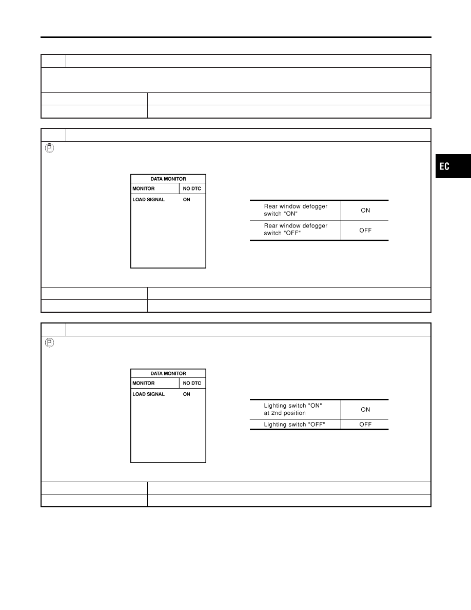
CHECK LOAD SIGNAL CIRCUIT OVERALL FUNCTION-I
With CONSULT-II
1. Turn ignition switch “ON”.
2. Check “LOAD SIGNAL” in “DATA MONITOR” mode with CONSULT-II under the following conditions.
SEF229Y
OK or NG
OK
©
GO TO 3.
NG
©
GO TO 6.
3
CHECK LOAD SIGNAL CIRCUIT OVERALL FUNCTION-II
With CONSULT-II
1. Turn ignition switch “ON”.
2. Check “LOAD SIGNAL” in “DATA MONITOR” mode with CONSULT-II under the following conditions.
SEF230Y
OK or NG
OK
©
INSPECTION END
NG
©
GO TO 10.
GI
MA
EM
LC
FE
CL
MT
AT
AX
SU
BR
ST
RS
BT
HA
SC
EL
IDX
ELECTRICAL LOAD SIGNAL
Diagnostic Procedure
EC-627