Infiniti G20 (P11). Manual - part 243
ECM Terminals and Reference Value
NCEC0646
Specification data are reference values and are measured between each terminal and ground.
CAUTION:
Do not use ECM ground terminals when measuring input/output voltage. Doing so may result in dam-
age to the ECM’s transistor. Use a ground other than ECM terminals, such as the ground.
TERMI-
NAL
NO.
WIRE
COLOR
ITEM
CONDITION
DATA (DC Voltage)
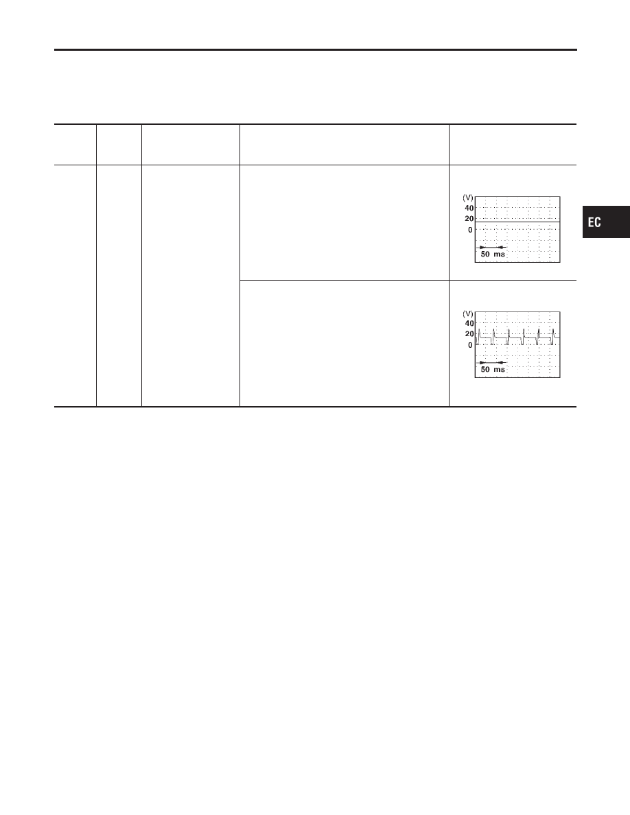
14
P
EVAP canister purge
volume control sole-
noid valve
[Engine is running]
I
Idle speed
BATTERY VOLTAGE
(11 - 14V)
SEF994U
[Engine is running]
I
Engine speed is about 2,000 rpm (More than 100
seconds after starting engine)
BATTERY VOLTAGE
(11 - 14V)
SEF995U
On Board Diagnosis Logic
NCEC0533
Malfunction is detected when an improper voltage signal is sent to
ECM through the valve.
Possible Cause
NCEC0534
I
Harness or connectors
(The valve circuit is open or shorted.)
I
EVAP canister purge volume control solenoid valve
GI
MA
EM
LC
FE
CL
MT
AT
AX
SU
BR
ST
RS
BT
HA
SC
EL
IDX
DTC P0443 EVAP CANISTER PURGE VOLUME CONTROL SOLENOID VALVE
(CIRCUIT)
ECM Terminals and Reference Value
EC-383