Infiniti G20 (P11). Manual - part 143
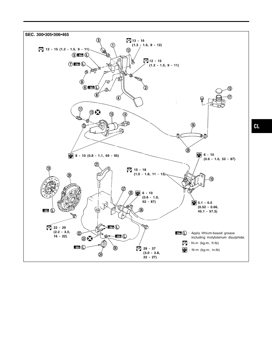
Components
NCCL0005
SCL818
1.
Clutch pedal bracket
2.
ASCD clutch switch
3.
Clutch interlock switch
4.
Clutch pedal
5.
Bush
6.
Clevis pin
7.
Assist spring
8.
Stopper rubber
9.
Bush
10. Clutch master cylinder
11. Nipple
12. Snap pin
13. Seal
14. Clevis
15. Reservoir cap
16. Hose
17. Reservoir tank
18. Clutch damper
19. Clutch disc
20. Clutch cover
21. Withdrawal lever
22. Clutch lever
23. Spring pin
24. Release bearing
25. Operating cylinder
26. Clutch hose
27. Spacer
28. Release bearing spring
29. Hose clamp
GI
MA
EM
LC
EC
FE
MT
AT
AX
SU
BR
ST
RS
BT
HA
SC
EL
IDX
CLUTCH SYSTEM
Components
CL-5