Infiniti G20 (P11). Manual - part 144
Installation
NCCL0009
1.
Connect clutch tube to master cylinder assembly, and hand-
tighten flare nut.
2.
Install master cylinder assembly to vehicle, and tighten mount-
ing nuts to the specified torque.
: 8 - 10 N·m (0.8 - 1.1 kg-m, 69 - 95 in-lb)
3.
Tighten reservoir tank bracket mounting bolts.
: 5.1 - 6.5 N·m (0.52 - 0.66 kg-m, 45.1 - 57.3 in-lb)
4.
Tighten clutch tube flare nut using a flare nut torque wrench.
: 15 - 18 N·m (1.5 - 1.8 kg-m, 11 - 13 ft-lb)
5.
After installing clevis pin, install snap pin to connect clutch
pedal to push rod.
6.
After finishing the operation, bleed air from clutch piping.
(Refer to “Bleeding Procedure”, CL-7.)
SCL725
Disassembly
NCCL0010
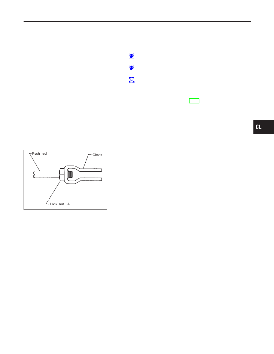
1.
Loosen push rod lock nut A to remove clevis and lock nut A.
2.
Remove dust cover.
3.
Remove stopper ring and stopper, and remove push rod from
cylinder body. During removal, keep push rod depressed, to
prevent piston inside master cylinder from popping out.
4.
Remove piston assembly from cylinder body.
Inspection
NCCL0011
Inspect for the following, and replace parts if necessary.
I
Damage, wear, rust, and pinholes on the cylinder inner wall
I
Damage and deformation of the reservoir tank
I
Weak spring
I
Crack and deformation of the dust cover
Assembly
NCCL0012
1.
Apply rubber lubricant to the sliding part of piston assembly,
and insert piston assembly.
2.
After installing stopper to push rod, install stopper ring while
keeping piston assembly depressed by hand, so that piston
assembly will not pop out.
CAUTION:
Stopper ring cannot be reused. Always use a new stopper ring
for assembly.
3.
Install dust cover.
GI
MA
EM
LC
EC
FE
MT
AT
AX
SU
BR
ST
RS
BT
HA
SC
EL
IDX
CLUTCH MASTER CYLINDER
Installation
CL-9