Infiniti G20 (P11). Manual - part 9


  Index      Infiniti     Infiniti G20 (P11) - service repair manual 1999-2002 year


Search            


Content   ..  7  8  9  10   ..


Infiniti G20 (P11). Manual - part 9


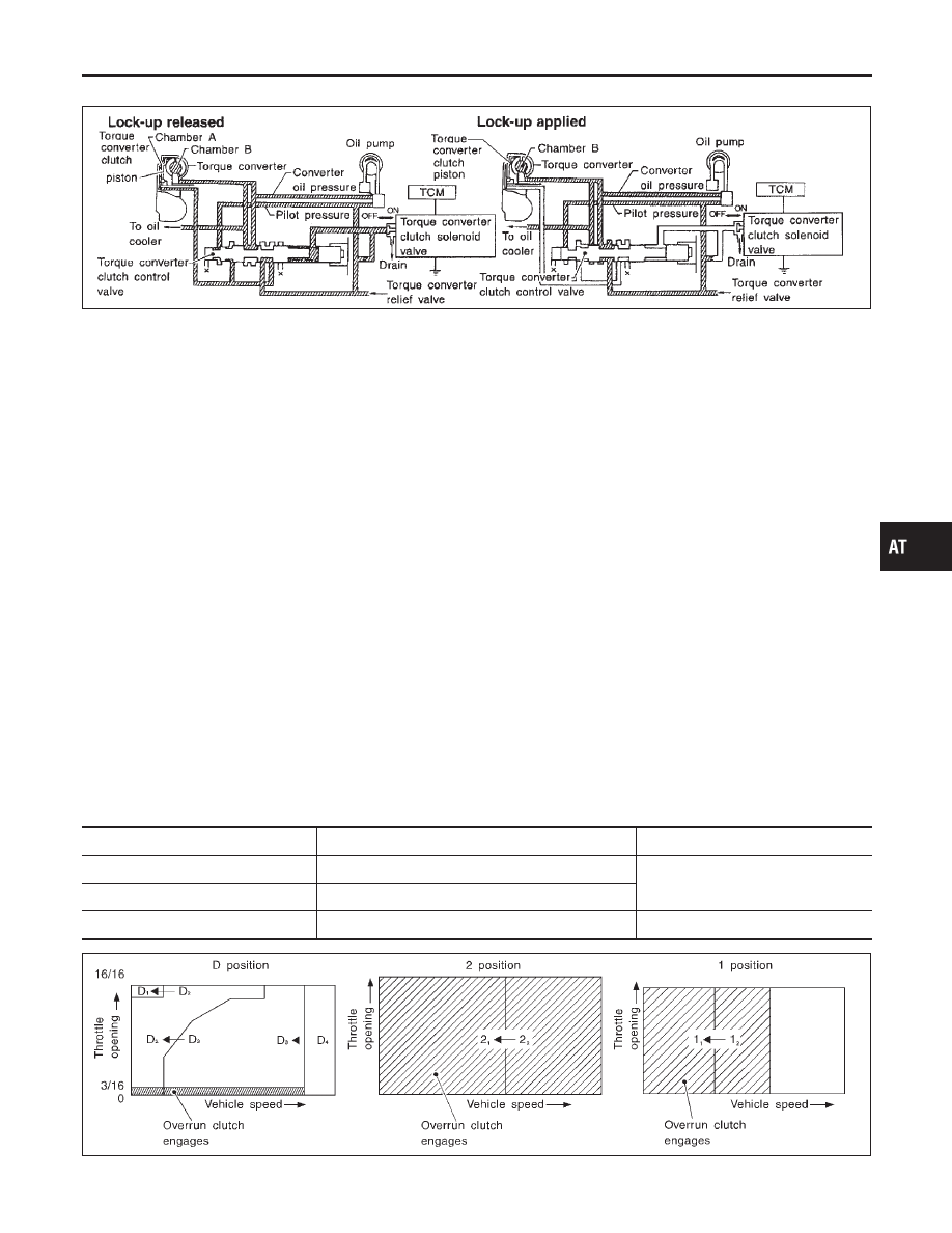
Torque Converter Clutch Control Valve Operation

NCAT0015S0303

AAT155A

Lock-up released
The OFF-duration of the torque converter clutch solenoid valve is
long, and pilot pressure is high. The pilot pressure pushes the end
face of the torque converter clutch control valve in combination with
spring force to move the valve to the left. As a result, converter
pressure is applied to chamber A (torque converter clutch piston
release side). Accordingly, the torque converter clutch piston
remains unlocked.
Lock-up applied
When the OFF-duration of the torque converter clutch solenoid
valve is short, pilot pressure drains and becomes low. Accordingly,
the control valve moves to the right by the pilot pressure of the
other circuit and converter pressure. As a result, converter pres-
sure is applied to chamber B, keeping the torque converter clutch
piston applied.
Also smooth lock-up is provided by transient application and
release of the lock-up.

OVERRUN CLUTCH CONTROL (ENGINE BRAKE
CONTROL)

NCAT0015S04

Forward one-way clutch is used to reduce shifting shocks in down-
shifting operations. This clutch transmits engine torque to the
wheels. However, drive force from the wheels is not transmitted to
the engine because the one-way clutch rotates idle. This means the
engine brake is not effective.
The overrun clutch operates when the engine brake is needed.

Overrun Clutch Operating Conditions

NCAT0015S0401

Selector lever position

Gear position

Throttle opening

“D” position

D

1

, D

2

, D

3

gear position

Less than 3/16

“2” position

2

1

, 2

2

gear position

“1” position

1

1

, 1

2

gear position

At any position

SAT014J

GI

MA

EM

LC

EC

FE

CL

MT

AX

SU

BR

ST

RS

BT

HA

SC

EL

IDX

OVERALL SYSTEM

Control Mechanism (Cont’d)

AT-33

SAT015J

Overrun Clutch Solenoid Valve Control

NCAT0015S0402

The overrun clutch solenoid valve is operated by an ON-OFF sig-
nal transmitted by the TCM to provide overrun clutch control
(engine brake control).
When this solenoid valve is “ON”, the pilot pressure drain port
closes. When it is “OFF”, the drain port opens.
During the solenoid valve “ON” pilot pressure is applied to the end
face of the overrun clutch control valve.

SAT016J

Overrun Clutch Control Valve Operation

NCAT0015S0403

When the solenoid valve is “ON”, pilot pressure is applied to the
overrun clutch control valve. This pushes up the overrun clutch
control valve. The line pressure is then shut off so that the clutch
does not engage.
When the solenoid valve is “OFF”, pilot pressure is not generated.
At this point, the overrun clutch control valve moves downward by
spring force. As a result, overrun clutch operation pressure is pro-
vided by the overrun clutch reducing valve. This causes the over-
run clutch to engage.
In the 1 position, the overrun clutch control valve remains pushed
down so that the overrun clutch is engaged at all times.

Control Valve

NCAT0016

FUNCTION OF CONTROL VALVES

NCAT0016S01

Valve name

Function

Pressure regulator valve, plug and
sleeve

Regulates oil discharged from the oil pump to provide optimum line pressure for all driving
conditions.

Pressure modifier valve and
sleeve

Used as a signal supplementary valve to the pressure regulator valve. Regulates pressure-
modifier pressure (signal pressure) which controls optimum line pressure for all driving condi-
tions.

Pilot valve

Regulates line pressure to maintain a constant pilot pressure level which controls lock-up
mechanism, overrun clutch, shift timing.

Accumulator control valve

Regulates accumulator back-pressure to pressure suited to driving conditions.

Manual valve

Directs line pressure to oil circuits corresponding to select positions.
Hydraulic pressure drains when the shift lever is in Neutral.

Shift valve A

Simultaneously switches four oil circuits using output pressure of shift solenoid valve A to
meet driving conditions (vehicle speed, throttle opening, etc.).
Provides automatic downshifting and up-shifting (1st

,

2nd

,

3rd

,

4th gears/4th

,

3rd

,

2nd

,

1st gears) in combination with shift valve B.

OVERALL SYSTEM

Control Mechanism (Cont’d)

AT-34

Valve name

Function

Shift valve B

Simultaneously switches three oil circuits using output pressure of shift solenoid valve B in
relation to driving conditions (vehicle speed, throttle opening, etc.).
Provides automatic downshifting and up-shifting (1st

,

2nd

,

3rd

,

4th gears/4th

,

3rd

,

2nd

,

1st gears) in combination with shift valve A.

Overrun clutch control valve

Switches hydraulic circuits to prevent engagement of the overrun clutch simultaneously with
application of the brake band in D

4

. (Interlocking occurs if the overrun clutch engages during

D

4

.)

1st reducing valve

Reduces low & reverse brake pressure to dampen engine-brake shock when down-shifting
from the “1” position 1

2

to 1

1

.

Overrun clutch reducing valve

Reduces oil pressure directed to the overrun clutch and prevents engine-brake shock.
In “1” and “2” positions, line pressure acts on the overrun clutch reducing valve to increase
the pressure-regulating point, with resultant engine brake capability.

Torque converter relief valve

Prevents an excessive rise in torque converter pressure.

Torque converter clutch control
valve, plug and sleeve

Activates or inactivates the lock-up function.
Also provides smooth lock-up through transient application and release of the lock-up system.

1-2 accumulator valve and piston

Dampens the shock encountered when 2nd gear band servo contracts, and provides smooth
shifting.

3-2 timing valve

Switches oil pressure with 3-2 timing valve according to throttle opening.

Shuttle control valve

Reduces shock when down-shifting from 3rd to 2nd and regulates overrun clutch.

Cooler check valve

Regulates oil pressure which causes lock-up when driving at low speeds.

GI

MA

EM

LC

EC

FE

CL

MT

AX

SU

BR

ST

RS

BT

HA

SC

EL

IDX

OVERALL SYSTEM

Control Valve (Cont’d)

AT-35

Introduction

NCAT0017

The A/T system has two self-diagnostic systems.
The first is the emission-related on board diagnostic system (OBD-II) performed by the TCM in combination
with the ECM. The malfunction is indicated by the MIL (malfunction indicator lamp) and is stored as a DTC in
the ECM memory but not the TCM memory.
The second is the TCM original self-diagnosis indicated by the O/D OFF indicator lamp. The malfunction is
stored in the TCM memory. The detected items are overlapped with OBD-II self-diagnostic items. For detail,
refer to AT-41.

OBD-II Function for A/T System

NCAT0018

The ECM provides emission-related on board diagnostic (OBD-II) functions for the A/T system. One function
is to receive a signal from the TCM used with OBD-related parts of the A/T system. The signal is sent to the
ECM when a malfunction occurs in the corresponding OBD-related part. The other function is to indicate a
diagnostic result by means of the MIL (malfunction indicator lamp) on the instrument panel. Sensors, switches
and solenoid valves are used as sensing elements.
The MIL automatically illuminates in One or Two Trip Detection Logic when a malfunction is sensed in rela-
tion to A/T system parts.

One or Two Trip Detection Logic of OBD-II

NCAT0019

ONE TRIP DETECTION LOGIC

NCAT0019S01

If a malfunction is sensed during the first test drive, the MIL will illuminate and the malfunction will be stored
in the ECM memory as a DTC. The TCM is not provided with such a memory function.

TWO TRIP DETECTION LOGIC

NCAT0019S02

When a malfunction is sensed during the first test drive, it is stored in the ECM memory as a 1st trip DTC
(diagnostic trouble code) or 1st trip freeze frame data. At this point, the MIL will not illuminate. — First Trip
If the same malfunction as that experienced during the first test drive is sensed during the second test drive,
the MIL will illuminate. — Second Trip
A/T-related parts for which the MIL illuminates during the first or second test drive are listed below.

Items

MIL

One trip detection

Two trip detection

Shift solenoid valve A — DTC: P0750

X

Shift solenoid valve B — DTC: P0755

X

Throttle position sensor or switch — DTC: P1705

X

Except above

X

The “trip” in the “One or Two Trip Detection Logic” means a driving mode in which self-diagnosis is performed
during vehicle operation.

OBD-II Diagnostic Trouble Code (DTC)

NCAT0020

HOW TO READ DTC AND 1ST TRIP DTC

NCAT0020S01

DTC and 1st trip DTC can be read by the following methods.
(

with CONSULT-II or

GST) CONSULT-II or GST (Generic Scan Tool) Examples: P0705, P0710, P0720,

P0725, etc.
These DTCs are prescribed by SAE J2012.
(CONSULT-II also displays the malfunctioning component or system.)

I

1st trip DTC No. is the same as DTC No.

I

Output of the diagnostic trouble code indicates that the indicated circuit has a malfunction.
However, in case of the Mode II and GST they do not indicate whether the malfunction is still
occurring or occurred in the past and returned to normal.
CONSULT-II can identify them as shown below. Therefore, using CONSULT-II (if available) is rec-
ommended.

Samples of CONSULT-II display for DTC and 1st trip DTC are shown in the next page. DTC or 1st trip DTC
of a malfunction is displayed in SELF DIAGNOSIS mode for “ENGINE” with CONSULT-II. Time data indicates
how many times the vehicle was driven after the last detection of a DTC.

ON BOARD DIAGNOSTIC SYSTEM DESCRIPTION

Introduction

AT-36


Content   ..  7  8  9  10   ..