Infiniti G20 (P11). Manual - part 10
 

  Index      Infiniti     Infiniti G20 (P11) - service repair manual 1999-2002 year


Search            


Content   ..  8  9  10  11   ..


Infiniti G20 (P11). Manual - part 10


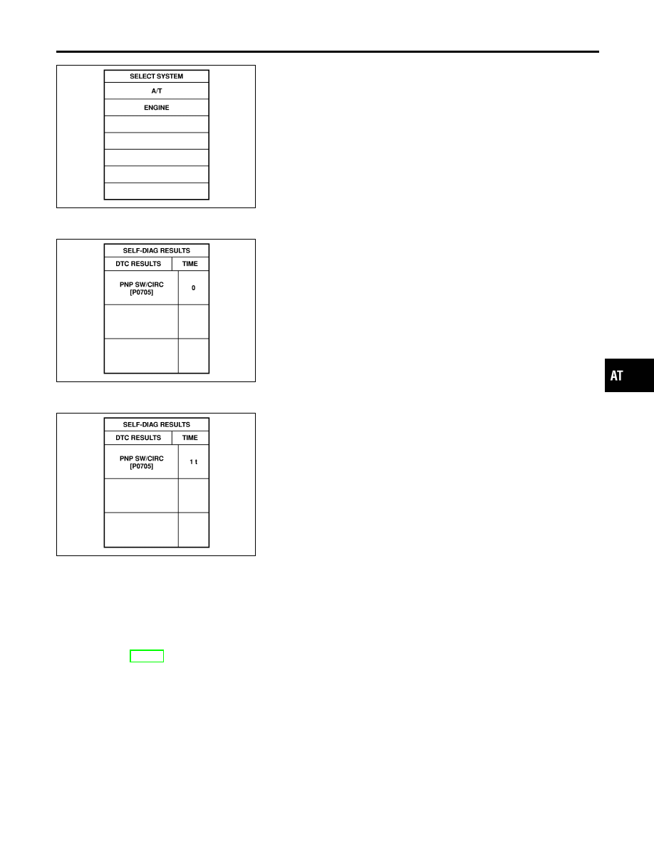
SAT014K

If the DTC is being detected currently, the time data will be “0”.

SAT015K

If a 1st trip DTC is stored in the ECM, the time data will be “245”.

SAT016K

Freeze Frame Data and 1st Trip Freeze Frame Data

NCAT0020S0101

The ECM has a memory function, which stores the driving condition such as fuel system status, calculated
load value, engine coolant temperature, short term fuel trim, long term fuel trim, engine speed and vehicle
speed at the moment the ECM detects a malfunction.
Data which are stored in the ECM memory, along with the 1st trip DTC, are called 1st trip freeze frame data,
and the data, stored together with the DTC data, are called freeze frame data and displayed on CONSULT-II
or GST. The 1st trip freeze frame data can only be displayed on the CONSULT-II screen, not on the GST. For
detail, refer to EC-88, “CONSULT-II”.
Only one set of freeze frame data (either 1st trip freeze frame data of freeze frame data) can be stored in the
ECM. 1st trip freeze frame data is stored in the ECM memory along with the 1st trip DTC. There is no prior-
ity for 1st trip freeze frame data and it is updated each time a different 1st trip DTC is detected. However, once
freeze frame data (2nd trip detection/MIL on) is stored in the ECM memory, 1st trip freeze frame data is no
longer stored. Remember, only one set of freeze frame data can be stored in the ECM.
The ECM has the following priorities to update the data.

GI

MA

EM

LC

EC

FE

CL

MT

AX

SU

BR

ST

RS

BT

HA

SC

EL

IDX

ON BOARD DIAGNOSTIC SYSTEM DESCRIPTION

OBD-II Diagnostic Trouble Code (DTC) (Cont’d)

AT-37

Priority

Items

1

Freeze frame data

Misfire — DTC: P0300 - P0306
Fuel Injection System Function — DTC: P0171, P0172, P0174, P0175

2

Except the above items (Includes A/T related items)

3

1st trip freeze frame data

Both 1st trip freeze frame data and freeze frame data (along with the DTCs) are cleared when the ECM
memory is erased.

HOW TO ERASE DTC

NCAT0020S02

The diagnostic trouble code can be erased by CONSULT-II, GST or ECM DIAGNOSTIC TEST MODE as
described following.

I

If the battery terminal is disconnected, the diagnostic trouble code will be lost within 24 hours.

I

When you erase the DTC, using CONSULT-II or GST is easier and quicker than switching the mode
selector on the ECM.

The following emission-related diagnostic information is cleared from the ECM memory when erasing DTC
related to OBD-II. For details, refer to EC-68, “Emission-related Diagnostic Information”.

I

Diagnostic trouble codes (DTC)

I

1st trip diagnostic trouble codes (1st trip DTC)

I

Freeze frame data

I

1st trip freeze frame data

I

System readiness test (SRT) codes

I

Test values

HOW TO ERASE DTC (WITH CONSULT-II)

NCAT0020S03

I

If a DTC is displayed for both ECM and TCM, it needs to be erased for both ECM and TCM.

1. If the ignition switch stays “ON” after repair work, be sure to turn ignition switch “OFF” once. Wait at least

10 seconds and then turn it “ON” (engine stopped) again.

2. Turn CONSULT-II “ON” and touch “A/T”.
3. Touch “SELF DIAGNOSIS”.
4. Touch “ERASE”. (The DTC in the TCM will be erased.) Then touch “BACK” twice.
5. Touch “ENGINE”.
6. Touch “SELF DIAGNOSIS”.
7. Touch “ERASE”. (The DTC in the ECM will be erased.)

ON BOARD DIAGNOSTIC SYSTEM DESCRIPTION

OBD-II Diagnostic Trouble Code (DTC) (Cont’d)

AT-38

SAT286K

HOW TO ERASE DTC (WITH GST)

NCAT0020S04

1. If the ignition switch stays “ON” after repair work, be sure to turn ignition switch “OFF” once. Wait at least

10 seconds and then turn it “ON” (engine stopped) again.

2. Perform “OBD-II SELF-DIAGNOSTIC PROCEDURE (No Tools)”. Refer to AT-49. (The engine warm-up

step can be skipped when performing the diagnosis only to erase the DTC.)

3. Select Mode 4 with Generic Scan Tool (GST). For details, refer to EC-101, “Generic Scan Tool (GST)”.

HOW TO ERASE DTC (NO TOOLS)

NCAT0020S05

1. If the ignition switch stays “ON” after repair work, be sure to turn ignition switch “OFF” once. Wait at least

10 seconds and then turn it “ON” (engine stopped) again.

2. Perform “TCM SELF-DIAGNOSTIC PROCEDURE (No Tools)”. Refer to AT-49. (The engine warm-up step

can be skipped when performing the diagnosis only to erase the DTC.)

GI

MA

EM

LC

EC

FE

CL

MT

AX

SU

BR

ST

RS

BT

HA

SC

EL

IDX

ON BOARD DIAGNOSTIC SYSTEM DESCRIPTION

OBD-II Diagnostic Trouble Code (DTC) (Cont’d)

AT-39

SAT964I

Malfunction Indicator Lamp (MIL)

=NCAT0021

1.

The malfunction indicator lamp will light up when the ignition
switch is turned ON without the engine running. This is for
checking the lamp.

I

If the malfunction indicator lamp does not light up, refer to
EL-98, “Warning Lamps”.
(Or see MIL & CONSULT-II in EC section. Refer to EC-81,
“Description”, “Malfunction Indicator Lamp (MIL)” and EC-88,
“CONSULT-II”.)

2.

When the engine is started, the malfunction indicator lamp
should go off.
If the lamp remains on, the on board diagnostic system has
detected an emission-related (OBD-II) malfunction. For detail,
refer

to

EC-67,

“ON

BOARD

DIAGNOSTIC

SYSTEM

DESCRIPTION”.

CONSULT-II

NCAT0022

After performing “SELF-DIAGNOSTIC PROCEDURE (WITH CON-
SULT-II)” (AT-41), place check marks for results on the “DIAGNOS-
TIC WORKSHEET”, AT-58. Reference pages are provided follow-
ing the items.
NOTICE:
1)

The CONSULT-II electrically displays shift timing and lock-up
timing (that is, operation timing of each solenoid).
Check for time difference between actual shift timing and the
CONSULT-II display. If the difference is noticeable, mechani-
cal parts (except solenoids, sensors, etc.) may be malfunction-
ing. Check mechanical parts using applicable diagnostic pro-
cedures.

2)

Shift schedule (which implies gear position) displayed on
CONSULT-II and that indicated in Service Manual may differ
slightly. This occurs because of the following reasons:

I

Actual shift schedule has more or less tolerance or allowance,

I

Shift schedule indicated in Service Manual refers to the point
where shifts start, and

I

Gear position displayed on CONSULT-II indicates the point
where shifts are completed.

3)

Shift solenoid valve “A” or “B” is displayed on CONSULT-II at
the start of shifting. Gear position is displayed upon completion
of shifting (which is computed by TCM).

4)

Additional CONSULT-II information can be found in the Opera-
tion Manual supplied with the CONSULT-II unit.

ON BOARD DIAGNOSTIC SYSTEM DESCRIPTION

Malfunction Indicator Lamp (MIL)

AT-40


Content   ..  8  9  10  11   ..