Infiniti FX35 / FX45. Manual - part 629


  Index      Infiniti     Infiniti FX35 / FX45 (S50) - service repair manual 2008 year


Search            


Content   ..  627  628  629  630   ..


Infiniti FX35 / FX45. Manual - part 629


OIL PAN AND OIL STRAINER

EM-33

< SERVICE INFORMATION >

[VQ35DE]

C

D

E

F

G

H

I

J

K

L

M

A

EM

N

P

O

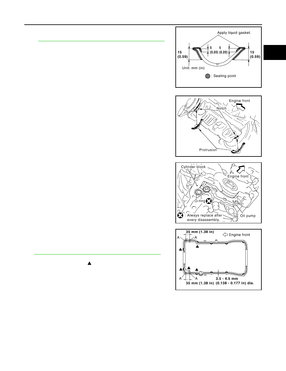
• Apply liquid gasket to oil pan gaskets as shown in the figure.

Use Genuine RTV Silicone Sealant or equivalent. Refer to

GI-44, "Recommended Chemical Product and Sealant"

.

• To install, align protrusion of oil pan gasket with notches of

front timing chain case and rear oil seal retainer.

• Install oil pan gasket with smaller arc to front timing chain case

side.

c.

Install new O-rings on the bottom of cylinder block and oil pump.

d.

Apply a continuous bead of liquid gasket with the tube presser
(commercial service tool) to the cylinder block mating surface of
oil pan (upper) to a limited portion as shown in the figure.
Use Genuine RTV Silicone Sealant or equivalent. Refer to

GI-44, "Recommended Chemical Product and Sealant"

.

CAUTION:

• For bolt holes with   marks (5 locations), apply liquid

gasket outside the holes.

• Apply a bead of 4.5 to 5.5 mm (0.177 to 0.217 in) in diame-

ter to area “A”.

• Attaching should be done within 5 minutes after coating.

e.

Install oil pan (upper).

CAUTION:

Install avoiding misalignment of both oil pan gaskets and O-rings.

PBIC2630E

PBIC1145E

PBIC1144E

PBIC2300E

EM-34

< SERVICE INFORMATION >

[VQ35DE]

OIL PAN AND OIL STRAINER

• Tighten mounting bolts in numerical order as shown in the fig-

ure.

• There are two types of mounting bolts. Refer to the following

for locating bolts.

f.

Tighten transmission joint bolts. Refer to 

AT-241, "Removal and Installation (2WD Models)"

.

2.

Install oil strainer to oil pump.

3.

Install oil pan (lower) as follows:

a.

Use scraper to remove old liquid gasket from mating surfaces.
• Also remove old liquid gasket from mating surface of oil pan

(upper).

• Remove old liquid gasket from the bolt holes and thread.

CAUTION:

Do not scratch or damage the mating surfaces when clean-
ing off old liquid gasket.

b.

Apply a continuous bead of liquid gasket with the tube presser
(commercial service tool) to the oil pan (lower) as shown in the
figure.
Use Genuine RTV Silicone Sealant or equivalent. Refer to

GI-44, "Recommended Chemical Product and Sealant"

.

CAUTION:

Attaching should be done within 5 minutes after coating.

c.

Install oil pan (lower).

M8 

×

 100 mm (3.94 in)

: 5, 7, 8, 11

M8 

×

 25 mm (0.98 in)

: Except the above

PBIC0783E

SEM958F

PBIC2657E

OIL PAN AND OIL STRAINER

EM-35

< SERVICE INFORMATION >

[VQ35DE]

C

D

E

F

G

H

I

J

K

L

M

A

EM

N

P

O

• Tighten mounting bolts in numerical order as shown in the fig-

ure.

4.

Install oil pan drain plug.
• Refer to the figure of components of former page for installation direction of drain plug washer. Refer to

EM-30, "Component (2WD Models)"

.

5.

Install in the reverse order of removal after this step.
NOTE:
At least 30 minutes after oil pan is installed, pour engine oil.

INSPECTION AFTER INSTALLATION

1.

Check the engine oil level and adjust engine oil. Refer to 

LU-5, "Inspection"

.

2.

Start engine, and check there is no leak of engine oil.

3.

Stop engine and wait for 10 minutes.

4.

Check the engine oil level again. Refer to 

LU-5, "Inspection"

.

Component (AWD Models)

INFOID:0000000001325718

PBIC0782E

SBIA0567E

EM-36

< SERVICE INFORMATION >

[VQ35DE]

OIL PAN AND OIL STRAINER

Removal and Installation (AWD Models)

INFOID:0000000001325719

REMOVAL

CAUTION:

To avoid the danger of being scalded, never drain engine oil when the engine is hot.
NOTE:
To remove oil pan (lower) only, take step 5, then step 24. Removal of step 1, hood assembly (step 2) and step
4 are unnecessary.
1.

Remove front tire.

2.

Remove hood assembly. Refer to 

BL-13, "Fitting Adjustment"

.

3.

Remove front and rear engine undercover with power tool.

4.

Remove front cross bar with power tool. Refer to 

FSU-5, "On-Vehicle Inspection and Service"

.

5.

Drain engine oil. Refer to 

LU-7, "Changing Engine Oil"

.

CAUTION:

• Perform this step when the engine is cold.
• Do not spill engine oil on drive belts.

6.

Drain engine coolant. Refer to 

CO-10, "Changing Engine Coolant"

.

CAUTION:

• Perform this step when the engine is cold.
• Do not spill engine coolant on drive belts.

7.

Remove engine cover with power tool. Refer to 

EM-19, "Component"

.

8.

Remove air hose from air duct to mass air flow sensor side and electric throttle control actuator side.
Refer to 

EM-17, "Component"

.

9.

Remove drive belts. Refer to 

EM-15, "Removal and Installation"

.

10. Remove front drive shaft (LH and RH) and side shaft. Refer to 

FAX-13, "On-Vehicle Inspection"

.

11. Remove side shaft. Refer to 

FFD-14, "Removal and Installation (VQ35DE Models)"

.

12. Removal engine rear lower slinger, and install engine rear slinger [SST: 10006 31U00 (

)] to sling

engine assembly for positioning. Refer to 

EM-7, "Special Service Tool"

.

13. Remove front suspension member. Refer to  

FSU-16, "Removal and Installation"

.

14. Remove engine mounting bracket, engine mounting bracket (lower) and insulator. Refer to 

EM-112,

"Component (2WD Models)"

.

15. Remove front propeller shaft. Refer to 

PR-4, "On-Vehicle Inspection"

.

16. Remove oil filter and oil filter bracket. Refer to 

LU-10, "Component"

.

17. Remove alternator stay. Refer to 

SC-19, "System Description"

.

18. Remove idler pulley and bracket. Refer to 

EM-15, "Removal and Installation"

.

19. Disconnect oil cooler water hoses, and remove oil cooler water pipe mounting bolt. Refer to 

LU-12, "Com-

ponent"

.

20. Disconnect A/T fluid cooler hoses, and remove A/T fluid cooler tube. Refer to 

AT-241, "Removal and

Installation (2WD Models)"

.

21. Remove front final drive assembly. Refer to 

FFD-14, "Removal and Installation (VQ35DE Models)"

.

22. Remove starter motor. Refer to 

SC-8, "System Description"

.

1.

Oil pan gasket (rear)

2.

Oil pan (upper)

3.

O-ring

4.

Oil pan gasket (front)

5.

Oil filter

6.

Connector bolt

7.

Oil cooler

8.

O-ring

9.

Relief valve

10. Oil filter bracket

11.

Oil filter bracket gasket

12. Oil strainer

13. Drain plug

14. Drain plug washer

15. Oil pan (lower)

16. Rear plate cover

17. Crankshaft position sensor (POS)

18

O-ring (small)

19. O-ring (large)

20. Axle pipe

Slinger bolts:

 : 28.0 N·m (2.9 kg-m, 21 ft-lb)


Content   ..  627  628  629  630   ..