Infiniti FX35 / FX45. Manual - part 537


  Index      Infiniti     Infiniti FX35 / FX45 (S50) - service repair manual 2008 year


Search            


Content   ..  535  536  537  538   ..


Infiniti FX35 / FX45. Manual - part 537


DTC P0335 CKP SENSOR (POS)

EC-909

< SERVICE INFORMATION >

[VK45DE]

C

D

E

F

G

H

I

J

K

L

M

A

EC

N

P

O

1.

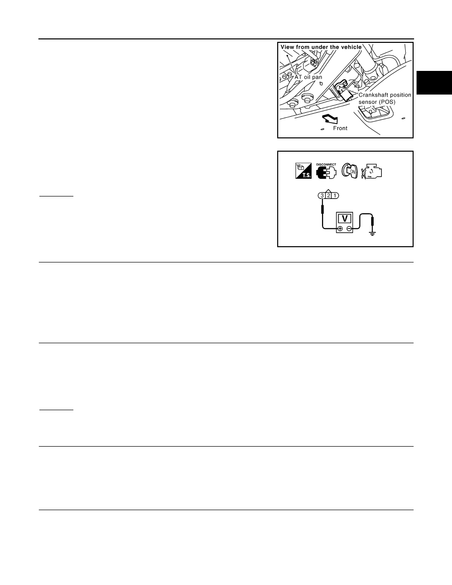
Disconnect crankshaft position (CKP) sensor (POS) harness
connector.

2.

Turn ignition switch ON.

3.

Check voltage between CKP sensor (POS) terminal 3 and
ground with CONSULT-III or tester.

OK or NG

OK

>> GO TO 4.

NG

>> GO TO 3.

3.

DETECT MALFUNCTIONING PART

Check the following.
• Harness connectors E211, M41
• Harness connectors F102, M82
• Harness for open or short between crankshaft position sensor (POS) and ECM 
• Harness for open or short between crankshaft position sensor (POS) and IPDM E/R

>> Repair open circuit or short to ground or short to power in harness or connectors.

4.

CHECK CKP SENSOR (POS) GROUND CIRCUIT FOR OPEN AND SHORT

1.

Turn ignition switch OFF.

2.

Check harness continuity between CKP sensor (POS) terminal 1 and ground.
Refer to Wiring Diagram.

3.

Also check harness for short to power.

OK or NG

OK

>> GO TO 6.

NG

>> GO TO 5.

5.

DETECT MALFUNCTIONING PART

Check the following.
• Harness connectors F102, M82
• Harness for open or short between crankshaft position sensor (POS) and ground 

>> Repair open circuit or short to power in harness or connectors.

6.

CHECK CKP SENSOR (POS) INPUT SIGNAL CIRCUIT FOR OPEN AND SHORT

1.

Disconnect ECM harness connector.

2.

Check harness continuity between ECM terminal 13 and CKP sensor (POS) terminal 2.
Refer to Wiring Diagram.

PBIB1483E

Voltage: Battery voltage

SEF481Y

Continuity should exist.

Continuity should exist.

EC-910

< SERVICE INFORMATION >

[VK45DE]

DTC P0335 CKP SENSOR (POS)

3.

Also check harness for short to ground and short to power.

OK or NG

OK

>> GO TO 7.

NG

>> Repair open circuit or short to ground or short to power in harness or connectors.

7.

CHECK CRANKSHAFT POSITION SENSOR (POS)

Refer to 

EC-910, "Component Inspection"

.

OK or NG

OK

>> GO TO 8.

NG

>> Replace crankshaft position sensor (POS).

8.

CHECK GEAR TOOTH

Visually check for chipping signal plate gear tooth.
OK or NG

OK

>> GO TO 9.

NG

>> Replace the signal plate.

9.

CHECK INTERMITTENT INCIDENT

Refer to 

EC-717

.

>> INSPECTION END

Component Inspection

INFOID:0000000001326744

CRANKSHAFT POSITION SENSOR (POS)

1.

Loosen the fixing bolt of the sensor.

2.

Disconnect crankshaft position sensor (POS) harness connector.

3.

Remove the sensor.

4.

Visually check the sensor for chipping.

5.

Check resistance as shown in the figure.

Removal and Installation

INFOID:0000000001326745

CRANKSHAFT POSITION SENSOR (POS)

Refer to 

AT-243, "Removal and Installation (AWD Models)"

.

PBIB0563E

Terminal No. (Polarity)

Resistance 

 [at 25

°

C (77

°

F)]

1 (+) - 2 (-)

Except 0 or 

1 (+) - 3 (-)

2 (+) - 3 (-)

PBIB0564E

DTC P0340 CAMSHAFT POSITION (CMP) SENSOR (PHASE)

EC-911

< SERVICE INFORMATION >

[VK45DE]

C

D

E

F

G

H

I

J

K

L

M

A

EC

N

P

O

DTC P0340 CAMSHAFT POSITION (CMP) SENSOR (PHASE)

Component Description

INFOID:0000000001326746

The camshaft position sensor (PHASE) senses the protrusion of
exhaust camshaft sprocket to identify a particular cylinder. The cam-
shaft position sensor (PHASE) senses the piston position.
When the crankshaft position sensor (POS) system becomes inoper-
ative, the camshaft position sensor (PHASE) provides various con-
trols of engine parts instead, utilizing timing of cylinder identification
signals.
The sensor consists of a permanent magnet and Hall IC.
When engine is running, the high and low parts of the teeth cause
the gap with the sensor to change.
The changing gap causes the magnetic field near the sensor to
change.
Due to the changing magnetic field, the voltage from the sensor changes.
ECM receives the signals as shown in the figure.

CONSULT-III Reference Value in Data Monitor Mode

INFOID:0000000001326747

Specification data are reference values.

On Board Diagnosis Logic

INFOID:0000000001326748

DTC Confirmation Procedure

INFOID:0000000001326749

NOTE:
If DTC Confirmation Procedure has been previously conducted, always turn ignition switch OFF and wait at
least 10 seconds before conducting the next test.
TESTING CONDITION:
Before performing the following procedure, confirm that battery voltage is more than 10.5V with igni-
tion switch ON.

1.

Crank engine for at least 2 seconds and run it for at least 5 seconds at idle speed.

2.

Check 1st trip DTC.

3.

If 1st trip DTC is detected, go to 

EC-913, "Diagnosis Procedure"

.

PBIB0562E

PBIB3459E

MONITOR ITEM

CONDITION

SPECIFICATION

ENG SPEED

• Run engine and compare CONSULT-III value with the tachometer indication.

Almost the same speed as 
the tachometer indication.

DTC No.

Trouble diagnosis name

DTC detecting condition

Possible cause

P0340
0340

Camshaft position sen-
sor (PHASE) circuit

• The cylinder No. signal is not sent to ECM for 

the first few seconds during engine cranking.

• The cylinder No. signal is not sent to ECM 

during engine running.

• The cylinder No. signal is not in the normal 

pattern during engine running.

• Harness or connectors

(The sensor circuit is open or shorted)

• Camshaft position sensor (PHASE)
• Camshaft sprocket (Exhaust)
• Starter motor (Refer to 

SC-8

.)

• Starting system circuit (Refer to 

SC-8

.)

• Dead (Weak) battery

EC-912

< SERVICE INFORMATION >

[VK45DE]

DTC P0340 CAMSHAFT POSITION (CMP) SENSOR (PHASE)

If 1st trip DTC is not detected, go to next step.

4.

Maintaining engine speed at more than 800 rpm for at least 5 seconds.

5.

Check 1st trip DTC.

6.

If 1st trip DTC is detected, go to 

EC-913, "Diagnosis Procedure"

.

Wiring Diagram

INFOID:0000000001326750

TBWM1337E


Content   ..  535  536  537  538   ..