Infiniti FX35 / FX45. Manual - part 263
BRC-38
< SERVICE INFORMATION >
[VDC/TCS/ABS]
TROUBLE DIAGNOSIS FOR SYSTEM
1.
Disconnect ABS actuator and electric unit (control unit) connector. Then reconnect it securely.
2.
Perform self-diagnosis again.
Do any self-diagnosis item appear?
YES
>> GO TO 3.
NO
>> Poor connection. Repair or replace the applicable connector.
3.
CHECK ABS MOTOR AND MOTOR RELAY POWER SUPPLY CIRCUIT
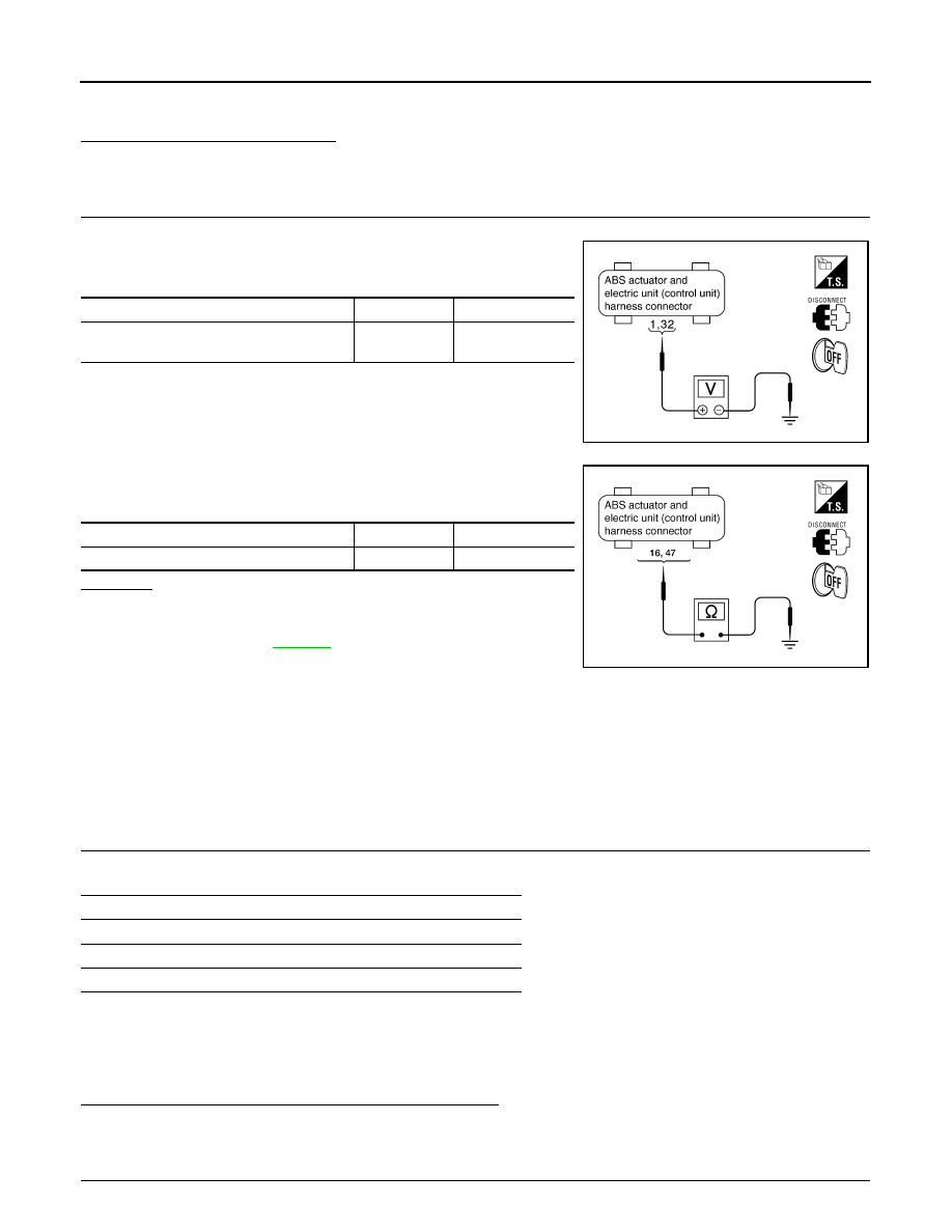
1.
Turn ignition switch OFF and disconnect ABS actuator and electric unit (control unit) connector E56.
2.
Check voltage between ABS actuator and electric unit (control
unit) harness connector and ground.
3.
Check continuity between ABS actuator and electric unit (control
unit) harness connector and ground.
OK or NG
OK
>> Perform self-diagnosis again. If the same result
appears, replace ABS actuator and electric unit (control
unit). Refer to
NG
>> Repair harness or connectors.
DTC C1113 G-SENSOR
INFOID:0000000001327682
CAUTION:
Sudden turns (such as spin turns, acceleration turns), drifting, etc. may cause the G sensor circuit
indicate a malfunction. However, this is not a malfunction, if normal operation can be resumed after
restarting engine.
INSPECTION PROCEDURE
1.
CHECK SELF-DIAGNOSTIC RESULTS
Check the self-diagnostic results.
CAUTION:
When on a turntable, such as at a parking structure entrance, or when on a moving object with engine
running, VDC OFF indicator lamp might turn on and self-diagnosis using CONSULT-III the yaw rate
sensor system might be displayed, but in this case there is no malfunction in yaw rate sensor circuit.
As soon as vehicle leaves turntable or moving object, restart engine to return the system to normal.
Is the above displayed in the self-diagnosis display items?
YES
>> GO TO 2.
NO
>> INSPECTION END
2.
CHECK CONNECTOR
ABS actuator and electric unit (control unit)
Ground
Voltage
1, 32
—
Battery voltage
(Approx. 12 V)
SFIA1198E
ABS actuator and electric unit (control unit)
Ground
Continuity
16, 47
—
Yes
SFIA1197E
Self-diagnostic results
YAW RATE SENSOR
SIDE G-SEN CIRCUIT
G-SENSOR (AWD models)