Infiniti FX35, FX50 (S51). Manual - part 609
SIDE OIL SEAL
DLN-271
< REMOVAL AND INSTALLATION >
[REAR FINAL DRIVE: R230]
C
E
F
G
H
I
J
K
L
M
A
B
DLN
N
O
P
SIDE OIL SEAL
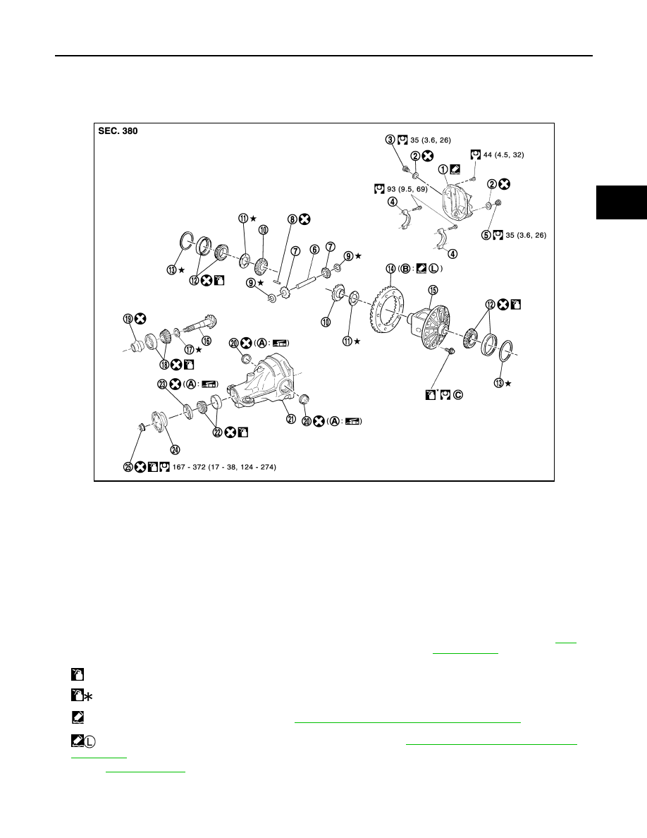
Exploded View
INFOID:0000000005249274
1.
Rear cover
2.
Gasket
3.
Filler plug
4.
Bearing cap
5.
Drain plug
6.
Pinion mate shaft
7.
Pinion mate gear
8.
Lock pin
9.
Pinion mate thrust washer
10. Side gear
11.
Side gear thrust washer
12. Side bearing
13. Side bearing adjusting washer
14. Drive gear
15. Differential case
16. Drive pinion
17. Pinion height adjusting washer
18. Pinion rear bearing
19. Collapsible spacer
20. Side oil seal
21. Gear carrier
22. Pinion front bearing
23. Front oil seal
24. Companion flange
25. Drive pinion lock nut
A.
Oil seal lip
B.
Screw hole
C.
Comply with the assembly proce-
dure when tightening. Refer to
: Apply gear oil.
: Apply anti-corrosion oil.
: Apply Genuine Silicone RTV or equivalent. Refer to
GI-16, "Recommended Chemical Products and Sealants"
.
: Apply Genuine High Strength Thread Locking Sealant or equivalent. Refer to
GI-16, "Recommended Chemical Products
Refer to
for symbols not described above.
JPDID0289GB