Infiniti FX35, FX50 (S51). Manual - part 608
FRONT OIL SEAL
DLN-267
< REMOVAL AND INSTALLATION >
[REAR FINAL DRIVE: R230]
C
E
F
G
H
I
J
K
L
M
A
B
DLN
N
O
P
Removal and Installation
INFOID:0000000005249273
REMOVAL
CAUTION:
Verify identification stamp of replacement frequency put in the lower part of gear carrier to determine
replacement for collapsible spacer when replacing front oil seal. Refer to “Identification stamp of
replacement frequency of front oil seal”. If collapsible spacer replacement is necessary, remove final
drive assembly and disassemble it to replace front oil seal and collapsible spacer. Refer to
NOTE:
The reuse of collapsible spacer is prohibited in principle. However, it is reusable on a one-time basis
only in cases when replacing front oil seal.
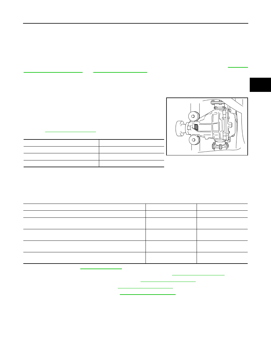
Identification stamp of replacement frequency of front oil seal
• The diagonally shaded area in the figure shows stamping point for
replacement frequency of front oil seal.
• The following table shows if collapsible spacer replacement is
needed before replacing front oil seal.
When collapsible spacer replacement is required, disassemble
final drive assembly to replace collapsible spacer and front oil seal.
Refer to
CAUTION:
Make a stamping after replacing front oil seal.
• After replacing front oil seal, make a stamping on the stamping point in accordance with the table below in
order to identify replacement frequency.
CAUTION:
Make a stamping from left to right.
1.
Drain gear oil. Refer to
.
2.
Remove the drive shafts from the rear final drive assembly. Refer to
.
3.
Remove the side flanges and side oil seals. Refer to
4.
Remove the rear propeller shaft. Refer to
5.
Measure the total preload torque. Refer to
NOTE:
Record the total preload torque measurement.
Stamp
collapsible spacer replacement
No stamp
Not required
“0” or “0” on the far right of stamp
Required
“01” or “1” on the far right of stamp
Not required
PDIA0976E
Stamp before stamping
Stamping on the far right
Stamping
No stamp
0
0
“0”
(Front oil seal was replaced once.)
1
01
“01”
(Collapsible spacer and front oil seal were replaced last time.)
0
010
“0” is on the far right.
(Only front oil seal was replaced last time.)
1
...01
“1” is on the far right.
(Collapsible spacer and front oil seal were replaced last time.)
0
...010