Infiniti FX35, FX50 (S51). Manual - part 395


  Index      Infiniti     Infiniti FX35, FX50 (S51) - service repair manual 2010 year


Search            


Content   ..  393  394  395  396   ..


Infiniti FX35, FX50 (S51). Manual - part 395


CCS-400

< SYSTEM DESCRIPTION >

[FCW]

DIAGNOSIS SYSTEM (LANE CAMERA UNIT)

DIAGNOSIS SYSTEM (LANE CAMERA UNIT)

CONSULT-III Function (LANE CAMERA)

INFOID:0000000005502035

DESCRIPTION

CONSULT-III performs the following functions by communicating with the lane camera unit.

WORK SUPPORT

Cause of Auto-Cancel Display Item List

When LDP control is canceled under the operating condition, “CAUSE OF AUTO-CANCEL” is memorized.
• Last five cancel (system cancel) causes are displayed.
• “CAUSE OF AUTO-CANCEL” displays the number of times of ignition switch ON/OFF up to a maximum of

“39”. “39” is kept even when the number exceeds “39”. The number returns to 0 when detecting the same
cancellation causes are detected. 
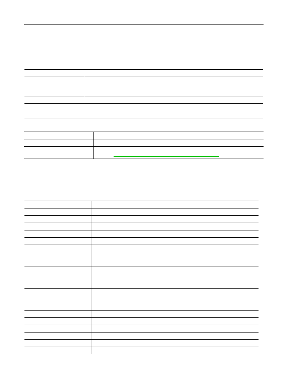
Select diag mode 

Function

Work support

• Performs the camera aiming.
• Displays causes of automatic cancellation of the LDP function.

Self Diagnostic Result

Displays memorized DTC in the lane camera unit.

Data Monitor

Displays real-time data of lane camera unit.

Active Test

Enables operation check of electrical loads by sending driving signal to them.

Ecu Identification

Displays part number of lane camera unit.

Work support item

Function

CAUSE OF AUTO-CANCEL

Indicates causes of automatic cancellation of the LDP.

AUTO AIM

Outputs camera unit, calculates dislocation of the camera, and displays adjustment direction. 
Refer to 

CCS-445, "CAMERA AIMING ADJUSTMENT : Description"

.

Cause of cancellation

Description

NO RECORD

Operating VDC/ABS

VDC or ABS function was operated.

Vehicle dynamics

Vehicle behavior exceeds specified value.

Steering speed

Steering speed was more than the specified value in evasive direction.

End by yaw angle

Yaw angle was the end of LDP control.

Departure yaw large

Detected more than the specified value of yaw angle in departure direction. 

ICC WARNING

Target approach warning of ICC system or IBA system was activated.

VDC OFF SW

VDC OFF switch was pressed.

CURVATURE

Road curve was more than the specified value.

Steering angle large

Steering angle was more than the specified value.

ICC main SW hold ON

ICC MAIN switch was held ON for more than a certain period.

Brake is operated

Brake pedal was operated.

Lateral offset

Distance of vehicle and lane was detached in lateral direction more than the specified value.

Lane marker lost

Lane camera unit lost the trace of lane marker.

Lane marker unclear

Detected lane marker was unclear.

Bank

Road bank angle was more than the specified value.

Yaw acceleration

Detected yawing speed was more than the specified value.

Deceleration large

Deceleration in a longitudinal direction was more than the specified value.

Accel is operated

Accelerator pedal was depressed.

Departure steering

Steering wheel was steered more than the specified value in departure direction.

CCS

DIAGNOSIS SYSTEM (LANE CAMERA UNIT)

CCS-401

< SYSTEM DESCRIPTION >

[FCW]

C

D

E

F

G

H

I

J

K

L

M

B

N

P

A

SELF DIAGNOSTIC RESULT

Displays memorized DTC in lane camera unit. Refer to 

CCS-516, "DTC Index"

.

DATA MONITOR

ACTIVE TEST

CAUTION:

• Never perform the active test while driving.
• Active test cannot be started while the lane departure warning lamp is illuminated.

Evasive steering

Steering wheel was steered more than the specified value in the evasive direction.

R range

Selector lever was operated to R range.

Parking brake drift

Rear wheels lock was detected.

Not operating condition

Did not meet the operating condition (vehicle speed, turn signal operation, etc.).

Monitored Item [unit]

Description

LDW SW

[On/Off]

Switch status judged from LDW switch signal
NOTE:
Shared with the FCW system

LDW ON LAMP

[On/Off]

Signal output status of LDW ON indicator
NOTE:
Shared with the FCW system

LDP ON IND

[On/Off]

Request signal status of LDP ON indicator lamp

LANE DPRT W/L

[On/Off]

Request signal status of lane departure warning lamp

BUZZER OUTPUT

[On/Off]

Signal output status of lane departure warning buzzer

LC INACCURAT

[On/Off]

Lane camera unit status

CAM HIGH TEMP

[On/Off]

Status of lane camera unit high temperature judgment

VHCL SPD SE

[km/h] or [mph]

Vehicle speed received from ABS actuator and electric unit (control unit) via CAN communi-
cation

TURN SIGNAL

[Off/LH/RH]

Status of “Turn signal” determined from BCM via CAN communication

LANE DETCT LH

[On/Off]

Left side lane marker detection

LANE DETCT RH

[On/Off]

Right side lane marker detection

CROSS LANE LH

[On/Off]

Condition that the vehicle is crossing left lane marker

CROSS LANE RH

[On/Off]

Condition that the vehicle is crossing right lane marker

WARN LANE LH

[On/Off]

Warning for left lane marker

WARN LANE RH

[On/Off]

Warning for right lane marker

VALID POS LH

[VLD/INVLD]

Lateral position for left lane marker is valid

VALID POS RH

[VLD/INVLD]

Lateral position for right lane marker is valid

AIMING DONE

[OK/NG] 

Status that camera aiming is done

AIMING RESULT

[OK/NOK] 

Result of camera aiming

XOFFSET

[pixel] 

Lane camera unit installation condition

CHK AIM YAW

[deg] 

Check result of camera aiming

CHK AIM ROLL

[deg] 

Check result of camera aiming

CHK AIM PITCH

[deg] 

Check result of camera aiming

FCTRY AIM YAW

[deg] 

Lane camera unit installation condition

FCTRY AIM ROL

[deg] 

Lane camera unit installation condition

FCTRY AIM PIT

[deg] 

Lane camera unit installation condition

CCS-402

< SYSTEM DESCRIPTION >

[FCW]

DIAGNOSIS SYSTEM (LANE CAMERA UNIT)

NOTE:

“Active test” of indicator/warning lamp cannot be performed when applicable indicator/warning lamp is turned ON.

Active test item

Operation

Description

BUZZER DRIVE

On

Outputs the voltage to sound the lane departure warning buzzer.

Off

Stops the voltage to sound the lane departure warning buzzer.

LDW ON IND

On

Outputs the voltage to illuminate the LDW ON indicator (on the LDW switch).
NOTE:
Shared with the FCW system

Off

Stops the voltage to illuminate the LDW ON indicator.

LDP ON IND

On

Requests the LDP ON indicator lamp ON [on the combination meter (Green)] to com-
bination meter (through unified meter and A/C amp.) via CAN communication.

Off

Stops the illumination request.

LANE DEPARTURE W/L

On

Requests the lane departure warning lamp ON [on the combination meter (Yellow)] 
to combination meter (through unified meter and A/C amp.) via CAN communication.

Off

Stops the illumination request.

CCS

ICC SENSOR INTEGRATED UNIT

CCS-403

< ECU DIAGNOSIS INFORMATION >

[FCW]

C

D

E

F

G

H

I

J

K

L

M

B

N

P

A

ECU DIAGNOSIS INFORMATION

ICC SENSOR INTEGRATED UNIT

Reference Value

INFOID:0000000005502036

VALUES ON THE DIAGNOSIS TOOL

Monitor item

Condition

Value/Status

MAIN SW

Ignition switch ON

When MAIN switch is pressed

On

When MAIN switch is not pressed

Off

SET/COAST SW

Ignition switch ON

When SET/COAST switch is pressed

On

When SET/COAST switch is not pressed

Off

CANCEL SW

Ignition switch ON

When CANCEL switch is pressed

On

When CANCEL switch is not pressed

Off

RESUME/ACC SW

Ignition switch ON

When RESUME/ACCELERATE switch is pressed

On

When RESUME/ACCELERATE switch is not pressed

Off

DISTANCE SW

Ignition switch ON

When DISTANCE switch is pressed

On

When DISTANCE switch is not pressed

Off

CRUISE OPE

Drive the vehicle and operate 
the ICC system.

When ICC system is controlling

On

When ICC system is not controlling

Off

BRAKE SW

Ignition switch ON

When brake pedal is depressed

Off

When brake pedal is not depressed

On

STOP LAMP SW

Ignition switch ON

When brake pedal is depressed

On

When brake pedal is not depressed

Off

IDLE SW

Engine running

Idling

On

Except idling (depress accelerator pedal)

Off

SET DISTANCE

• Start the engine and turn the 

ICC system ON.

• Press the DISTANCE 

switch to change the vehi-
cle-to-vehicle distance set-
ting.

When set to “long”

Long

When set to “middle”

Mid

When set to “short”

Short

CRUISE LAMP

Start the engine and press 
MAIN switch.

ICC system ON
(MAIN switch indicator ON)

On

ICC system OFF
(MAIN switch indicator OFF)

Off

OWN VHCL

Start the engine and press 
MAIN switch.

ICC system ON
(Own vehicle indicator ON)

On

ICC system OFF
(Own vehicle indicator OFF)

Off

VHCL AHEAD

Drive the vehicle and activate 
the vehicle-to-vehicle distance 
control mode.

When a vehicle ahead is detected (vehicle ahead de-
tection indicator ON)

On

When a vehicle ahead is not detected (vehicle ahead 
detection indicator OFF)

Off

ICC WARNING

Start the engine and press the 
MAIN switch.

When ICC system is malfunctioning
 (ICC system warning lamp ON)

On

When ICC system is normal
 (ICC system warning lamp OFF)

Off

VHCL SPEED SE

While driving

Value of vehicle 

speed signal 

(wheel speed)


Content   ..  393  394  395  396   ..