Content .. 1758 1759 1760 1761 ..
Infiniti FX35, FX50 (S51). Manual - part 1760
ST-32
< REMOVAL AND INSTALLATION >
STEERING GEAR AND LINKAGE
a.
Apply recommended sealant into the thread of inner socket.
Use Genuine Silicone RTV or equivalent.
9.
Screw inner socket into rack part and tighten at the specified torque.
10. Decide on the neutral position of the rack stroke (L).
11. Install rear cover cap to gear sub-assembly.
CAUTION:
Make sure that the projection of rear cover cap is aligned
with the marking position of gear housing assembly.
12. Apply recommended thread sealant to the thread of adjusting
screw (2 turns thread), and then screw in the adjusting screw
until it reaches height “H” from gear housing assembly mea-
sured before disassembling.
Use Genuine High Performance Thread Sealant or equiva-
lent.
13. Move rack assembly 10 strokes throughout the full stroke so that
the parts can fit with each other.
14. Adjust pinion rotating torque with the following procedure.
a.
Measure pinion rotating torque within
±
180
°
of neutral position
of the rack assembly using Tools. Stop the gear at the point
where highest torque is read.
b.
Loosen adjusting screw and retighten to 5.4 N·m (0.55 kg-m, 48
in-lb), and then loosen by 20 to 40
°
.
c.
Measure pinion rotating torque using tools to make sure that the
measured value is within the standard. Readjust if the value is
outside the standard. Replace steering gear assembly, if the
value is outside the standard after readjusting, or adjusting
screw rotating torque is 5 N·m (0.51 kg-m, 44 in-lb) or less.
d.
Apply recommended sealant to inner socket and turn pinion fully to left with inner socket installed to gear
housing assembly.
Standard
L
: Refer to
.
SGIA0877E
SGIA0624E
A: Preload gauge [SST: ST3127S000 (J-25765-A)]
B: Preload adapter [SST: KV48103400 (
—
)]
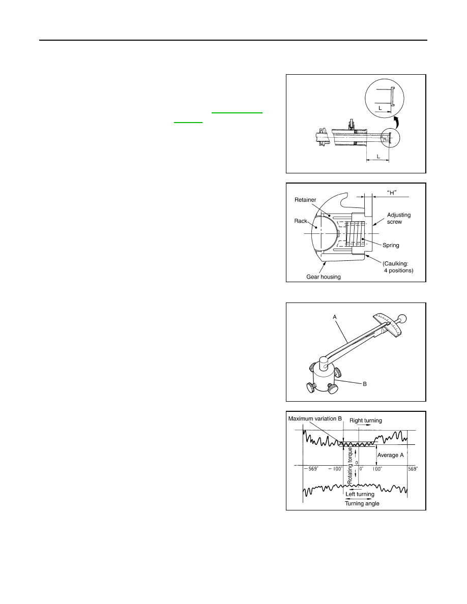
SGIA1383E
Pinion rotating torque
Around neutral position
(within
±
100
°
) average “A”
: 2.27 – 3.05 N·m (0.24 –
0.31 kg-m, 20 – 26 in-lb)
Maximum variation “B”
: 0.98 N·m (0.10 kg-m, 9.0
in-lb)
SGIA0936E