Infiniti FX35, FX50 (S51). Manual - part 98


  Index      Infiniti     Infiniti FX35, FX50 (S51) - service repair manual 2010 year


Search            


Content   ..  96  97  98  99   ..


Infiniti FX35, FX50 (S51). Manual - part 98


AV

SYSTEM

AV-165

< SYSTEM DESCRIPTION >

[NAVIGATION (SINGLE MONITOR)]

C

D

E

F

G

H

I

J

K

L

M

B

A

O

P

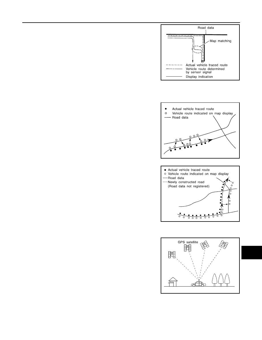
Map-matching repositions the vehicle on the road map when a new
location is judged to be more accurate. This is done by comparing
the current vehicle position (calculated by the normal position detec-
tion method) from the map data stored in the HDD (Hard Disk Drive).

There is a possibility that the vehicle position may not be corrected in the following case, and when vehicle is
driven over a certain distance or time in which GPS information is hard to receive. Correct manually the cur-
rent location mark on the screen.
• In map-matching, several alternative routes are prepared and pri-

oritized in addition to the road judged as currently driving on.
Therefore, due to errors in the distance and/or direction, an incor-
rect road may be prioritized, and the current location mark may be
repositioned to the incorrect road.
If two roads are running in parallel, they are of the same priority.
Therefore, the current location mark may appear on either of them
alternately, depending on maneuvering of the steering wheel and
configuration of the road, etc.

• Map-matching does not function correctly when road on which the

vehicle is driving is new, etc. and not recorded in the map data.
Also, map-matching does not function correctly when road pattern
stored in the map data and the actual road pattern are different due
to repair, etc.
Therefore, the map-matching function judges other road as a cur-
rently driving road if the road is not in the map, and displays the
current location mark on it. Later, the current location mark may be
repositioned to the road if the correct road is detected.

• Effective range for comparing the vehicle position and travel direc-

tion calculated by the distance and direction with the road data is
limited. Therefore, correction by map-matching is not possible
when there is an excessive gap between current vehicle position and the position on the map.

GPS (Global Positioning System)

GPS (Global Positioning System) is developed for and is controlled
by the US Department of Defense. The system utilizes GPS satel-
lites (NAVSTAR), transmitting out radio waves while flying on an orbit
around the earth at an altitude of approximately 21,000 km (13,049
mile).
The receiver calculates the travel position in three dimensions (lati-
tude/longitude/altitude) according to the time lag of the radio waves
that four or more GPS satellites transmit (three-dimensional position-
ing). The GPS receiver calculates the travel position in two dimen-
sions (latitude/longitude) with the previous altitude data if the GPS
receiver receives only three radio waves (two-dimensional position-
ing). GPS position correction is not performed while stopping the
vehicle.

Accuracy of the GPS will deteriorate under the following conditions:
• In two-dimensional positioning, GPS accuracy will deteriorate when altitude of the vehicle position changes.
• The position of GPS satellite affects GPS detection precision. The position detection may not be precisely

performed.

SEL685V

SEL686V

JSNIA0180GB

SEL526V

AV-166

< SYSTEM DESCRIPTION >

[NAVIGATION (SINGLE MONITOR)]

SYSTEM

• The position detection is not performed if GPS receiver does not receive radio waves from GPS satellites.

(Inside a tunnel, parking in a building, under an elevated highway etc.) GPS receiver may not receive radio
waves from GPS satellites if any object is placed on the GPS antenna.

NOTE:
• The detection result has an error of approximately 10 m (32.81 ft) even with a high-precision three dimen-

sional positioning.

• There may be cases when the accuracy is lowered and radio waves are stopped intentionally because the

GPS satellite signal is controlled by the US trace control center.

AUDIO FUNCTION

The audio system is equipped with the following functions. Each function is operated with multifunction switch,
preset switch, touch panel, steering switch or audio recognition. Operation status of audio is indicated at dis-
play.

Operating Signal

Audio system operation can be performed with multifunction switch, preset switch, steering switch, touch
panel function or voice recognition function.
• Operating signal is transmitted to AV control unit with AV communication when it is operated by multifunction

switch or preset switch. The disk ejection operating signal is performed by hardwire.

• Operating signal is transmitted to AV control unit with steering switch signal when it is operated by steering

switch.

Screen Display

Switching of display is performed with serial communication between display unit and AV control unit.

AM/FM Radio Mode

• AM/FM radio tuner is built into AV control unit.
• Audio signal is received by rod antenna, next it is amplified by antenna amp., and finally it is input to AV con-

trol unit. Audio signal is input to BOSE amp., and BOSE amp. outputs to each speaker.

Satellite Radio Mode

• Satellite radio tuner is built into AV control unit.
• Audio signal (satellite radio) is received by satellite antenna, and it is input to AV control unit. AV control unit

outputs audio signal to BOSE amp. The signal is also outputted from BOSE amp. to both woofer and each
speaker.

CD Mode

• CD function is built into AV control unit.
• AV control unit outputs audio signal to BOSE amp., and BOSE amp. outputs to each speaker when CD is

inserted to AV control unit.

Bluetooth

 Audio Mode

• Bluetooth

 audio function is built into AV control unit.

• Bluetooth

 audio can play music data in the portable audio by means of Bluetooth

 communications

between the portable audio and the AV control unit.

• AV control unit outputs audio signal to BOSE amp., and BOSE amp. outputs to each speaker.

Music Box Mode

• Music CD data is stored on HDD that is built into AV control unit, and it can be played.
• AV control unit outputs music (sound signal) that is stored on HDD to BOSE amp., and BOSE amp. outputs

to each speaker.

Driver's Audio Stage

FUNCTION

AM/FM radio

Satellite radio

CD

Bluetooth

 audio

Music Box (Hard Disk Drive)

Driver's Audio Stage

AV

SYSTEM

AV-167

< SYSTEM DESCRIPTION >

[NAVIGATION (SINGLE MONITOR)]

C

D

E

F

G

H

I

J

K

L

M

B

A

O

P

• Driver's Audio Stage controls the speaker's output characteristic by BOSE amp. so that the driver's seat is to

be the center of sounds.

• ON/OFF signals of Driver's Audio Stage are transmitted from AV control unit to BOSE amp. using mode

change signal.

DVD PLAY FUNCTION

• DVD is played by inserting DVD into the AV control unit.
• DVD image signals are transmitted to the display unit and DVD sound signals are transmitted to each

speaker via BOSE amp.

HANDS-FREE PHONE FUNCTION

• AV control unit includes hands-free phone function.
• Hands-free communication can be operated by connecting using Bluetooth

™ 

communication with cellular

phone.

• Operation is performed by steering switch, and operating condition is indicated on display.
• Guide sound that is heard during operation is input from AV control unit to BOSE amp., and is output from

front speaker and center speaker.

When A Call Is Originated

Spoken voice sound output from the microphone (microphone signal) is input to AV control unit. AV control unit
outputs to cellular phone with Bluetooth

 communication as a TEL voice signal. Voice sound is then heard at

the other party.

When Receiving A Call

Voice sound is input to own cellular phone from the other party. TEL voice signal is output to door speaker, and
the signal is input to BOSE amp. via AV control unit by establishing Bluetooth

 communication from cellular

phone.

AUXILIARY INPUT FUNCTION

• Image and sound can be output from an external device by connecting a device with auxiliary input jacks.
• AUX image signals are transmitted to the display unit and AUX sound signals are transmitted to each

speaker via BOSE amp.

USB CONNECTION FUNCTION

• Connecting iPod

®

 or USB memory allows the driver to play iPod

®

 music files or USB memory-stored music

files, video data, and image viewer data.

• Sound signals of music files stored in iPod

®

 or USB memory are transmitted from the USB connector to the

AV control unit. The AV control unit transmits the sound signals to the woofer and each speaker via BOSE
amp.

• Video signals and image viewer file signals are transmitted from the USB connector to the AV control unit.

The data and files are displayed on the front display unit screen.

• iPod

®

 is recharged when connected to USB connector.

• Only files that meet the following conditions will be played.

NOTE:
• iPod

®

 is a trademark of Apple inc., registered in the U.S. and other countries.

• Image signals cannot be received from iPod

®

.

• Use the enclosed USB harness when connecting iPod

®

 to USB connector.

VOICE RECOGNITION FUNCTION

• Each operation of multi AV system can be performed by inputting sound to microphone.
• Start of sound recognition system can be performed by steering switch.

TOUCH PANEL SYSTEM

Each operation of multi AV system can be performed by directly touching a display.

AROUND VIEW MONITOR FUNCTION

Music file

Video file

Image viewer file

File format

“MP3”, “WMA”, “AAC”, “M4A”

“DivX”, “MPEG4 (ASF)”

“JPEG”

File extension

“.mp3”, “.wma”, “.aac”, “.m4a”

“.divx”, “.afs”, “.avi”

“.jpg”, “.jpeg”

Maximum file size

2 GB

2 GB

2 MB

AV-168

< SYSTEM DESCRIPTION >

[NAVIGATION (SINGLE MONITOR)]

SYSTEM

• This system is equipped with wide-angle high-resolution cameras on the front and rear of the vehicle and on

both right and left door mirrors. The images from front view, rear view, front-side view (RH side), and birds-
eye view that shows the view from the top of the vehicle are displayed to monitor the vehicle surroundings. 

• Around view monitor control unit cuts out and expands the image received from each camera to create each

view. 

• The sonar indicator is displayed on display (superimposed on the camera image) in combination with the

camera assistance sonar system to warm of the approach of an obstacle. 

• In front view and rear view, the vehicle width, distance lines and predictive course lines are superimposed

and displayed. In front-side view, the vehicle distance guiding line and vehicle width guiding line are dis-
played. 

• The Birds-Eye view converts the images from 4 cameras into the overhead view and displays the status of

the vehicle on display. The vehicle icon and sonar indicator that are displayed on the Birds-Eye view display
are rendered by around view monitor control unit. 

Around View Monitor Screen

• Around view monitor combines and displays the travel direction view and “Birds-Eye view”, “Front-Side view”

and then it displays the sonar indicator on the “Birds-Eye view”, “Front-Side view”“Rear wide view”. 

• AV control unit renders the “Change View” switch, view icon, warning message on display. 

Screen constitution

Operation Description

• Around view monitor operates by pressing the “CAMERA” switch of multifunction switch and shifting the

selector switch to the reverse position. 

• When the selector lever is in any position other than the reverse position, the screen is switched to the

around view monitor by pressing the “CAMERA” switch.

• The screen is switched to the around view monitor by shifting the selector lever to the reverse position. 
• In the around view monitor, Birds-Eye view, Front-side view and rear wide view (rear only) can be switched

by pressing the “CAMERA” switch. 

• The around view monitor is cancelled 3 minutes after pressing the “CAMERA” switch, and then the screen

returns to the screen before displaying the around view monitor when selector lever is in a position other
than the reverse position.

• ON/OFF setting of sonar indicator display on the Front-Side view screen can be performed. 

JSNIA2332GB


Content   ..  96  97  98  99   ..