Infiniti EX35. Manual - part 388
 

  Index      Infiniti     Infiniti EX35 - service repair manual 2008 year


Search            


Content   ..  386  387  388  389   ..


Infiniti EX35. Manual - part 388


CCS

INTELLIGENT CRUISE CONTROL SYSTEM SYMPTOMS

CCS-87

< SYMPTOM DIAGNOSIS >

[INTELLIGENT CRUISE CONTROL]

C

D

E

F

G

H

I

J

K

L

M

B

N

P

A

SYMPTOM DIAGNOSIS

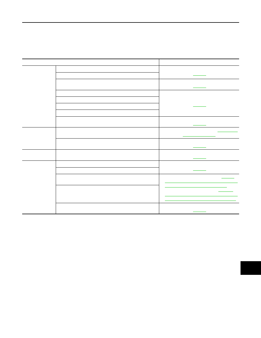
INTELLIGENT CRUISE CONTROL SYSTEM SYMPTOMS

Symptom Table

INFOID:0000000003130121

Symptoms

Reference page

Operation

MAIN switch does not turn ON.

Symptom 1

CCS-88

MAIN switch does not turn OFF.

Cruise does not function for setting (powering functions).

Symptom 2

CCS-90

CANCEL switch does not function.

Symptom 3

CCS-92

Resume does not function.

Set speed does not increase.

Set distance to the vehicle ahead cannot be changed.

ICC is not cancelled when the A/T selector lever is “N”.

Symptom 4

CCS-93

Display/Chime

Multi information display not appear. 

Check combination meter. Refer to 

MWI-38, "Di-

agnosis Description"

.

Chime does not function.

Symptom 5

CCS-95

Control

Driving force is hunting.

Symptom 6

CCS-97

Function to detect 
the vehicle ahead

System frequently cannot detect the vehicle ahead.

Symptom 7

CCS-98

Distance to detect the vehicle ahead is short.

System misidentifies a vehicle even though there is no vehicle 
ahead.

• Adjust laser beam aiming. Refer to 

CCS-8, 

"LASER BEAM AIMING ADJUSTMENT : Spe-
cial Repair Requirement (Preparation)"

.

• Perform ICC action test. Refer to 

CCS-13, 

"ACTION TEST : Special Repair Requirement 
(Vehicle-To-Vehicle Distance Control Mode)"

.

System misidentifies a vehicle in the next lane.

System does not detect a vehicle at all.

Symptom 8

CCS-99

CCS-88

< SYMPTOM DIAGNOSIS >

[INTELLIGENT CRUISE CONTROL]

MAIN SWITCH DOES NOT TURN ON, MAIN SWITCH DOES NOT TURN OFF

MAIN SWITCH DOES NOT TURN ON, MAIN SWITCH DOES NOT TURN
OFF

Description

INFOID:0000000003130122

MAIN SWITCH DOES NOT TURN ON

• ICC system display does not appear even when MAIN switch is pressed.

MAIN SWITCH DOES NOT TURN OFF

• When ICC system display is on, display does not turn off even if MAIN switch is pressed.
NOTE:
• ICC system is in fail-safe mode when ICC system warning lamp is turned on. Therefore, ICC system display

is not appeared even if MAIN switch is pressed.

•  Perform the self-diagnosis for ICC sensor integrated unit if ICC system warning lamp is illuminated. Repair

or replace applicable item.

Diagnosis Procedure

INFOID:0000000003130123

1.

CHECK MAIN SWITCH

With CONSULT-III

1.

Start engine.

2.

With “Data Monitor” of “ICC”, check if “MAIN SW” and “CRUISE LAMP” operate normally.

Is the inspection result normal?

YES

>> GO TO 2.

NO

>> GO TO 5.

2.

CHECK UNIFIED METER AND A/C AMP.

With CONSULT-III

With “Data Monitor” of “METER/M&A”, check if “CRUISE IND” operate normally.

Is the inspection result normal?

YES

>> GO TO 3.

NO

>> GO TO 5.

3.

PERFORM SELF-DIAGNOSIS OF UNIFIED METER AND A/C AMP.

1.

Perform self-diagnosis of unified meter and A/C amp.

2.

Check if DTC is detected. Refer to 

MWI-101, "DTC Index"

.

Is any DTC detected?

YES

>> Repair or replace applicable item.

NO

>> GO TO 4.

4.

PERFORM SELF-DIAGNOSIS MODE OF COMBINATION METER

1.

Perform self-diagnosis mode of combination meter. Refer to 

MWI-38, "Diagnosis Description"

.

2.

Check that the multi information display operates normally. 

3.

If it does not operate normally, repair the affected components or replace the combination meter. 

>> INSPECTION END

5.

PERFORM SELF-DIAGNOSIS OF ICC SENSOR INTEGRATED UNIT

1.

Perform self-diagnosis of ICC sensor integrated unit.

2.

Check if DTC “U1000: CAN COMM CIRCUIT” (DTC 100) is detected.

Is it DTC detected?

YES

>> GO TO 6.

NO

>> GO TO 7.

6.

CAN COMMUNICATION INSPECTION

Perform CAN communication system inspection. Repair or replace the applicable item. Refer to 

CCS-75,

"Diagnosis Procedure"

.

CCS

MAIN SWITCH DOES NOT TURN ON, MAIN SWITCH DOES NOT TURN OFF

CCS-89

< SYMPTOM DIAGNOSIS >

[INTELLIGENT CRUISE CONTROL]

C

D

E

F

G

H

I

J

K

L

M

B

N

P

A

>> INSPECTION END

7.

CHECK ICC STEERING SWITCH

Inspect ICC steering switch. Refer to 

CCS-40, "Diagnosis Procedure"

>> INSPECTION END

CCS-90

< SYMPTOM DIAGNOSIS >

[INTELLIGENT CRUISE CONTROL]

ICC SYSTEM CANNOT BE SET (MAIN SWITCH TURNS ON/OFF)

ICC SYSTEM CANNOT BE SET (MAIN SWITCH TURNS ON/OFF)

Description

INFOID:0000000003130124

ICC system cannot be set by pressing SET/COAST switch though MAIN switch can be turned ON/OFF. 
NOTE:
ICC system cannot be set in the following cases.
• When the vehicle speed is not in range of approx. 40 km/h (25 MPH) to 144 km/h (90 MPH).
• When the A/T selector lever is in “N”.
• While the brake is in operation.
• When the wiper switch is at LOW/HI position.

Diagnosis Procedure

INFOID:0000000003130125

1.

CHECK CAUSE OF AUTOMATIC CANCELLATION

With CONSULT-III

With “CAUSE OF AUTO-CANCEL” in “Work Support” at “ICC”, check if any cause of cancellation is found.

Is any cause found?

YES

>> GO TO 2.

NO

>> GO TO 3.

2.

CHECK RELEVANT CANCEL FACTORS

According to cancel cause, go to specified diagnosis.

>> INSPECTION END

3.

PERFORM SELF-DIAGNOSIS OF ICC SENSOR INTEGRATED UNIT

1.

Perform self-diagnosis of ICC sensor integrated unit.

2.

Check if DTC is detected. Refer to 

CCS-85, "DTC Index"

.

Is any DTC detected?

YES

>> GO TO 6.

NO

>> GO TO 4.

4.

CHECK SWITCHES AND VEHICLE SPEED SIGNAL

With CONSULT-III

1.

Start engine.

2.

With “Data Monitor” of “ICC”, check the following items for normal operation. 

-

VHCL SPEED SE

-

D RANGE SW

-

SET/COAST SW

-

BRAKE  SW

Is the inspection result normal?

YES

>> GO TO 7.

NO

>> GO TO 5.

5.

CHECK INOPERATIVE ITEMS

Check the items for which DATA MONITOR cannot operate normally

Cancel cause

Inspection item

OPE SW VOLT CIRC

Refer to 

CCS-40, "Diagnosis Procedure"

.

VHCL SPD UNMATCH

Refer to 

CCS-31, "Diagnosis Procedure"

.

IGN LOW VOLT

Refer to 

CCS-29, "Diagnosis Procedure"

.

ECM CIRCUIT

Refer to 

CCS-51, "Diagnosis Procedure"

.

CAN COMM ERROR

Refer to 

CCS-75, "Diagnosis Procedure"

.

ABS/TCS/VDC CIRC

Refer to 

CCS-33, "Diagnosis Procedure"

.

ECD CIRCUIT

Refer to 

CCS-61, "Diagnosis Procedure"

.


Content   ..  386  387  388  389   ..