Infiniti EX35. Manual - part 166


  Index      Infiniti     Infiniti EX35 - service repair manual 2008 year


Search            


Content   ..  164  165  166  167   ..


Infiniti EX35. Manual - part 166


AV

MULTI AV SYSTEM

AV-445

< FUNCTION DIAGNOSIS >

[BOSE AUDIO WITH NAVIGATION]

C

D

E

F

G

H

I

J

K

L

M

B

A

O

P

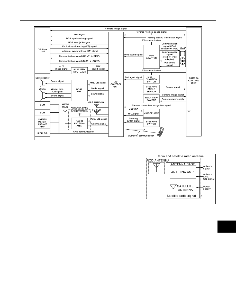
WITH REAR VIEW MONITOR

NOTE:
• The name MULTIFUNCTION SWITCH indicates the integration of PRESET SWITCH and MULTIFUNCTION

SWITCH virtually.

• A radio antenna base integrated with radio antenna and satellite

radio antenna is adopted.

JSNIA0695GB

JSNIA1062GB

AV-446

< FUNCTION DIAGNOSIS >

[BOSE AUDIO WITH NAVIGATION]

MULTI AV SYSTEM

WITH AROUND VIEW MONITOR

NOTE:
• The name MULTIFUNCTION SWITCH indicates the integration of PRESET SWITCH and MULTIFUNCTION

SWITCH virtually.

• A radio antenna base integrated with radio antenna and satellite

radio antenna is adopted.

System Description

INFOID:0000000003515918

Multi AV system means that the following systems are integrated.

JSNIA0696GB

JSNIA1062GB

System name

System explanation

NAVIGATION SYSTEM

AV-458, "System Description"

AUDIO SYSTEM

AV-453, "System Description"

REAR VIEW MONITOR SYSTEM

AV-463, "System Description"

VEHICLE INFORMATION SYSTEM

• Status of audio, climate control system, fuel economy, mainte-

nance and navigation are displayed.

• AV control unit displays the fuel consumption status while re-

ceiving data signal through CAN communication from ECM, uni-
fied meter and A/C amp.

• AV control unit is connected to BCM via CAN communication 

transmitting/receiving for the vehicle settings function.

HANDS-FREE PHONE SYSTEM

Refer to the following “HANDS-FREE PHONE SYSTEM”.

AUXILIARY INPUT SYSTEM

Refer to the following “AUXILIARY INPUT SYSTEM”.

AV

MULTI AV SYSTEM

AV-447

< FUNCTION DIAGNOSIS >

[BOSE AUDIO WITH NAVIGATION]

C

D

E

F

G

H

I

J

K

L

M

B

A

O

P

• AV control unit function by transmitting/receiving data one by one with each unit (slave unit) that configures

them completely as a master unit by connecting between units that configure MULTI AV system with two AV
communication lines (H, L).

• Around view monitor control unit transmits/receives the data signal with sonar control unit and controls sonar

control unit. Around view monitor control unit transmits the information received from sonar control unit to AV
control unit. (With around view monitor)

• Two AV communication lines (H, L) adopt a twisted pair line that is resistant to noise.
• AV control unit is connected by CAN communication, and it receives data signals from ECM, unified meter

and A/C amp. It computes and displays fuel economy information value with the obtained information. The
transmitting/receiving of data signal is performed by BCM. In addition, it transmits the required signal of vehi-
cle setting and receives the response signal.

• AV control unit is connected with display and serial communication, and it transmits the required signal of

display and display control and receives the response signal from display. Also, it is connected with satellite
radio by serial communication, and it transmits the operating signal and receives the display signal.

NOTE:
AV control unit can perform CONSULT-III self-operating function and on board self-diagnosis.
• CONSULT-III self diagnosis: Refer to 

AV-498, "CONSULT-III Function (MULTI AV)"

.

• On board self diagnosis: Refer to 

AV-482, "Diagnosis Description"

.

HANDS-FREE PHONE SYSTEM

• Hands-free communication can be operated by connecting using Bluetooth

®

 with cellular phone.

• Operation is performed by steering switch, and operating condition is indicated on display.
• Guide sound that is heard during operation is input from AV control unit to BOSE amp. and is output from

door speakers.

When a call is originated

Spoken voice sound output from the microphone (Mic. Signal) is input into AV control unit. AV control unit out-
puts to cellular phone with Bluetooth communication as a TEL voice signal. Voice sound is then heard by the
other party.

When receiving a call

Voice sound is input to one's own cellular phone from the other party. TEL voice signal is output to door speak-
ers, and the signal is input to BOSE amp. via AV control unit by establishing Bluetooth communication from
cellular phone.

AUXILIARY INPUT SYSTEM

• Image and sound can be output from an external device by connecting a device with auxiliary input jacks.

VOICE RECOGNITION SYSTEM

Refer to the following “VOICE RECOGNITION SYSTEM”.

TOUCH PANEL SYSTEM

Refer to the following “TOUCH PANEL SYSTEM”.

System name

System explanation

JPNIA0510GB

AV-448

< FUNCTION DIAGNOSIS >

[BOSE AUDIO WITH NAVIGATION]

MULTI AV SYSTEM

• Operation can be performed with multifunction switch and steering switch. Multifunction switch transmits

operation signal to AV control unit by AV communication.

VOICE RECOGNITION SYSTEM

• Each operation of multi AV system can be performed by inputting sound to microphone.
• Start of sound recognition system can be performed by steering switch.

TOUCH PANEL SYSTEM

Each operation of multi AV system can be performed by directly touching a display.

JSNIA0056GB

JSNIA0053GB

JSNIA0052GB


Content   ..  164  165  166  167   ..